Supercharge Your Innovation With Domain-Expert AI Agents!

Utility tunnel system

A technology of integrated pipe gallery and pipe gallery, which is applied in the field of municipal engineering, can solve problems such as many bolt connection points, large segment radii, and restrictions on large-scale promotion, and achieve lower installation and precision requirements, lower manufacturing and installation requirements, and reduced The effect of the cross-sectional size of the small pipe gallery

Pending Publication Date: 2018-05-08
MCC CAPITAL ENGINEERING & RESEARCH
View PDF10 Cites 0 Cited by
  • Summary
  • Abstract
  • Description
  • Claims
  • Application Information

AI Technical Summary

Problems solved by technology

[0003] The first type is a prefabricated reinforced concrete structure. Both the standard section of the pipe gallery and the node section of the pipe gallery adopt a prefabricated reinforced concrete structure. This structure has high requirements for mold precision, high prefabrication costs, and large-scale promotion is limited;
[0004] The second is the steel structure. Both the standard section of the pipe gallery and the joint section of the pipe gallery adopt a steel structure. The assembly-type manufacturing and installation requirements at the joints of the pipe gallery are relatively high, and the segments at the joints need to be turned and changed. The radius of the segment is large, the assembly is more complicated, and there are many bolt connection points, which are prone to leakage and other phenomena, and the production accuracy of the segment is required to be high

Method used


Image

  • Utility tunnel system
  • Utility tunnel system
  • Utility tunnel system

Examples


Embodiment Construction

[0026] In order to have a clearer understanding of the technical features, purposes and effects of the present invention, the specific implementation manners of the present invention will now be described with reference to the accompanying drawings.

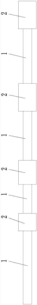
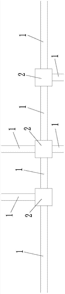
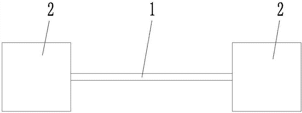
[0027] Such as figure 1 , figure 2 , image 3 As shown, the present invention provides a comprehensive pipe gallery system, which includes connected and connected standard sections 1 and node sections 2, the pipe gallery wall of the standard section 1 is a steel structure, and each node section 2 is connected to at least one standard section 1. The pipe corridor wall of node section 2 is a prefabricated reinforced concrete structure (also called a prefabricated reinforced concrete structure) or a cast-in-place reinforced concrete structure.

[0028] In the comprehensive pipe gallery system of the present invention, the pipe gallery wall of the standard section 1 adopts a steel structure, and the pipe gallery wall of the node s...


PUM


Abstract

The invention provides a utility tunnel system. The utility tunnel system comprises standard sections and joint sections, wherein the tunnel walls of the standard sections are of steel structures, each joint section is connected with at least one standard section, and the tunnel walls of the joint sections are of assembly type reinforced concrete structures or cast-in-place reinforced concrete structures. According to the utility tunnel system, the cost is low, large-scale promotion is facilitated, and the manufacturing and installing requirements of joints are low.

Description

technical field [0001] The invention relates to the technical field of municipal engineering, in particular to a comprehensive pipe gallery system. Background technique [0002] The current integrated pipe gallery system mostly adopts the following two types of structures: [0003] The first is the prefabricated reinforced concrete structure. Both the standard section of the pipe gallery and the node section of the pipe gallery adopt a prefabricated reinforced concrete structure. This structure requires high mold precision, high prefabrication costs, and large-scale promotion is limited; [0004] The second is the steel structure. Both the standard section of the pipe gallery and the joint section of the pipe gallery adopt steel structures. The assembly-type manufacturing and installation requirements at the joints of the pipe gallery are relatively high, and the segments at the joints need to be turned and changed. The segment radius is large, the assembly is more complica...

Claims


Application Information

Patent Timeline
IPC IPC(8): E02D29/045
CPCE02D29/045
Inventor 陈思王瑀
Owner MCC CAPITAL ENGINEERING & RESEARCH
Features
  • R&D
  • Intellectual Property
  • Life Sciences
  • Materials
  • Tech Scout
  • Unparalleled Data Quality
  • Higher Quality Content
  • 60% Fewer Hallucinations
Learn More