
Fiber composite material rib connecting piece

A technology of connectors and composite bars, which is applied in the direction of building components, building reinforcements, structural elements, etc., can solve problems such as hindering the application of FRP bars in concrete structures, reducing the performance and service life of FRP bars, and damage to the surface structure of FRP bars. Achieve the effect of avoiding fixed connection failure and surface structure damage

Pending Publication Date: 2018-05-08
CENT RES INST OF BUILDING & CONSTR CO LTD MCC GRP
View PDF0 Cites 3 Cited by
  • Summary
  • Abstract
  • Description
  • Claims
  • Application Information

AI Technical Summary

Problems solved by technology

[0007] On the one hand, although the corrosion resistance of FRP bars is better than that of steel bars, the corrosion resistance of iron wires is similar to that of steel bars, so it is inevitable that the fixed connection between FRP bars will fail due to the corrosion of iron wires, so that the reinforcement bars are easy to The fixed connection between the FRP bars fails, resulting in a significant drop in the bearing capacity of the concrete structure;
[0008] On the other hand, the bearing capacity of FRP tendons in the direction perpendicular to the fiber axis is weak, and when the bound iron wires are rigidly fixed to the FRP tendons, they will form a contact mode similar to line contact with the FRP tendons. And thus generate concentrated shear force, which will cause damage to the surface structure of FRP bars and reduce the performance and service life of FRP bars
[0009] Therefore, the steel bar to steel bar butt joint method used in the prior art cannot be applied to the field construction of FRP bars
This is also an important problem that hinders the application of FRP reinforced concrete structures in practical engineering.

Method used


Image

  • Fiber composite material rib connecting piece
  • Fiber composite material rib connecting piece
  • Fiber composite material rib connecting piece

Examples


Embodiment Construction

[0029] In order to make the technical solutions and advantages of the present invention clearer, the present invention will be further described in detail below in conjunction with the accompanying drawings and specific embodiments.

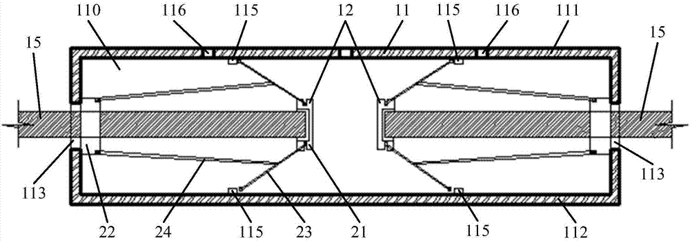
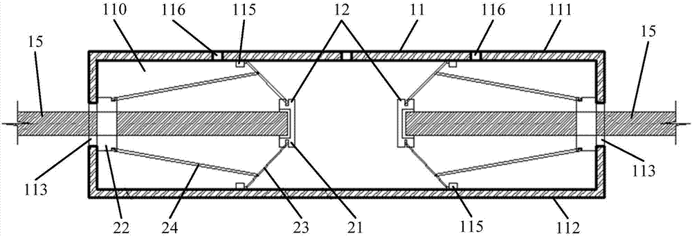
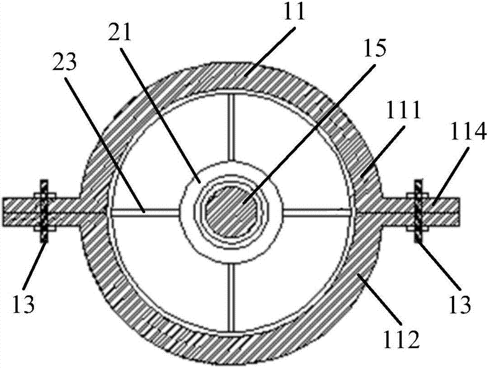
[0030] figure 1 It is a schematic structural diagram of the connectors of the fiber composite tendons in the embodiment of the present invention. figure 2 It is a schematic diagram when the anchor rod and the support rod on the umbrella-shaped anchoring device of the connector of the fiber composite tendon in the embodiment of the present invention are opened. image 3 It is a schematic cross-sectional view of the connector of the fiber composite tendon in the embodiment of the present invention. Such as Figure 1 ~ Figure 3 As shown, the connectors of the fiber composite tendon in the embodiment of the present invention include: a cylindrical sleeve 11, a bolt 13 and two umbrella-shaped anchoring devices 12;

[0031] The interior of the cyli...


PUM


Abstract

The invention provides a fiber composite material rib connecting piece. The fiber composite material rib connecting piece includes a tube-shaped sleeve, bolts and two umbrella-type anchor devices; thetube-shaped sleeve includes an upper sleeve and a lower sleeve; the upper sleeve is fixedly connected with the lower sleeve; the umbrella-type anchor devices include anchorage devices, sliding blocks, anchor rods and supporting rods; two anchor devices are separately and fixedly connected at the connecting ends of two to-be-connected fiber composite material ribs; one ends of the anchor rods arerotatably connected with the anchorage devices and the other ends of the anchor rods abut against locking blocks; one ends of the supporting rods are slidably connected with the anchor rods and the other ends of the supporting rods are rotatably connected with the sliding blocks; and the fiber composite material rib is sleeved with the sliding blocks which are fixedly connected with the pipe wallof the tube-shaped sleeve. According to the fiber composite material rib connecting piece, while a longitudinal connection between the fiber composite material ribs is completed, the problem that ironwires are corroded to generate failure of the fixed connection between the fiber composite material ribs can be avoided and meanwhile the problem that the damage of the surface structures of the fiber composite material ribs happens due to binding patterns can be avoided, and the performance and the service life of the fiber composite material ribs are improved.

Description

technical field [0001] The present application relates to the technical field of engineering construction, in particular to a connector for fiber composite tendons. Background technique [0002] Reinforced concrete structure is the most widely used structural form in engineering construction. During the construction of reinforced concrete structures, it is sometimes necessary to connect several reinforcing bars longitudinally, so as to meet the bearing capacity and use requirements of some special building structures. [0003] Steel bars and concrete are the main materials used in infrastructure construction in recent years, but the problems of corrosion and performance degradation of reinforced concrete structures and steel structures are becoming more and more serious, among which steel bar corrosion is the most common problem. The above problems not only affect the normal use and life of the building structure, but also may cause a large number of safety accidents or pot...

Claims


Application Information

Patent Timeline
Patent Type & Authority Applications(China)
IPC IPC(8): E04C5/16
CPCE04C5/165
Inventor 廉杰杨勇新岳清瑞赵进阶李彪侯慕轶
Owner CENT RES INST OF BUILDING & CONSTR CO LTD MCC GRP
Learn More