Annular double-sided tooth high-speed miniaturized driving linear motion module

A technology of motion modules and double-sided teeth, which is applied in the direction of gear transmission, transmission, friction transmission, etc., can solve the problems of limiting motion accuracy and speed, large installation space, and easy wear of meshing transmission tooth surfaces, etc., to achieve Guaranteed stability and rigidity, low maintenance costs, and guaranteed transmission strength

Pending Publication Date: 2018-05-08
GUANGZHOU CITY CONSTR COLLEGE
View PDF0 Cites 4 Cited by
  • Summary
  • Abstract
  • Description
  • Claims
  • Application Information

AI Technical Summary

Problems solved by technology

[0003] The first type is a screw, such as a ball screw, which has high motion and positioning accuracy, but requires a large installation space, limited speed, and high cost
[0004] The second type is synchronous belt drive, its precision is average, but the motor and mounting seat need to be installed in the direction of motion, and a certain space is required. When the stroke is too long or the load is too large, the tension and elastic deformation of the belt limit its movement. Accuracy and Speed
[0005] There is also a rack and pinion structure, but its meshing transmission tooth surface is easy to wear, the working sound is loud, and the accuracy and maintenance are also difficult.

Method used


Image

  • Annular double-sided tooth high-speed miniaturized driving linear motion module
  • Annular double-sided tooth high-speed miniaturized driving linear motion module
  • Annular double-sided tooth high-speed miniaturized driving linear motion module

Examples


Embodiment Construction

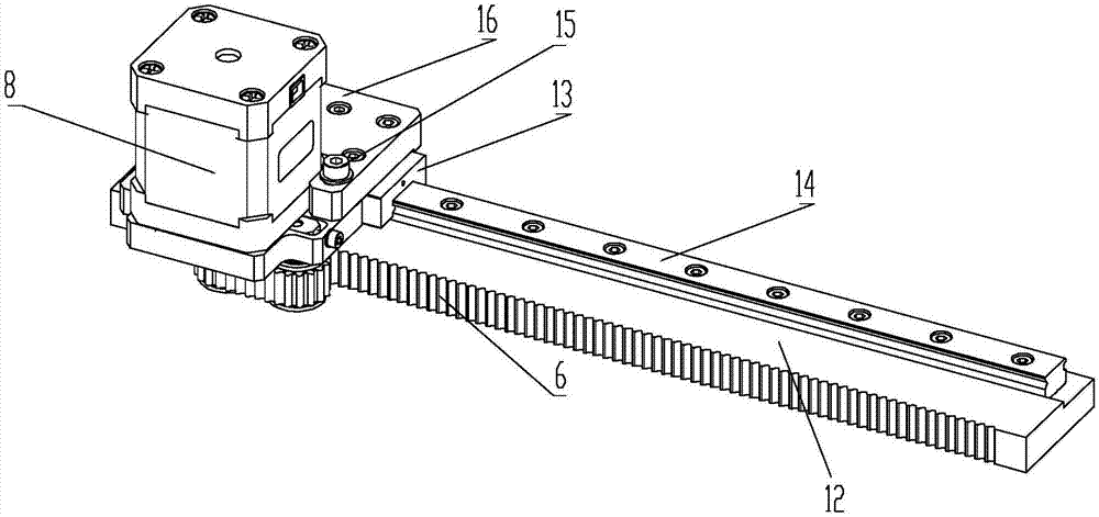
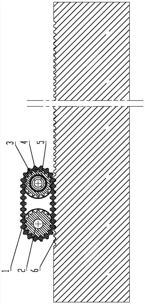
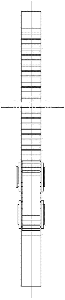
[0036] Such as Figure 1 to Figure 5 The circular double-sided gear high-speed miniaturized drive linear motion module shown includes a module base 12, a motor base 7, a drive motor 8, an annular double-sided tooth synchronous belt transmission mechanism and a guide mechanism, and the side surface of the module base 12 There is a linear synchronous rack and rack 6, the module base 12 and the synchronous rack and rack 6 are integrally processed and formed, the upper surface of the module base 12 is provided with a linear guide rail 14, the length direction of the linear guide rail 14 and the synchronous gear The length direction of the rack 6 is parallel, the motor base 7 is located above the module base 12, the drive motor 8 is installed on the motor base 7, and the ring-shaped double-sided tooth synchronous belt transmission mechanism is connected with the output shaft of the drive motor 8 and the motor base respectively. 7, and the annular double-sided tooth synchronous belt...


PUM


Abstract

The invention discloses an annular double-sided tooth high-speed miniaturized driving linear motion module. The linear motion module comprises a module base, a motor base, a driving motor, an annulardouble-sided tooth synchronous belt transmission mechanism and a guide mechanism, wherein a linear synchronous toothed rack is arranged on the side surface of the module base, and a linear guide railis arranged on the upper surface of the module base; the length direction of the linear guide rail is parallel to the length direction of the synchronous toothed rack; the motor base is arranged abovethe module base; the driving motor is installed on the motor base; the annular double-sided tooth synchronous belt transmission mechanism is connected with an output shaft of the driving motor and anidler wheel shaft which is locked with the motor base correspondingly, and the annular double-sided tooth synchronous belt transmission mechanism is meshed with the synchronous toothed rack; the guide mechanism is connected with the motor base and is clamped on the linear guide rail; and the driving motor can drive the annular double-sided tooth synchronous belt transmission mechanism to move forward or backward in the length direction of the synchronous toothed rack and perform accurate positioning.

Description

technical field [0001] The invention relates to a mechanical transmission motion device, in particular to a high-speed miniaturized drive linear motion module of an annular double-sided tooth. Background technique [0002] As we all know, in the mechanical structure, there are three kinds of transmission directions of the commonly used linear motion modules. [0003] The first type is a screw, such as a ball screw, which has high motion and positioning accuracy, but requires a large installation space, limited speed, and high cost. [0004] The second is synchronous belt transmission, its precision is general, but the motor and mounting seat need to be installed in the direction of movement, and a certain space is required. When the stroke is too long or the load is too large, the tension and elastic deformation of the belt limit its movement. Accuracy and speed. [0005] There is also a rack and pinion structure, but its meshing transmission tooth surface is easy to wear,...

Claims


Application Information

Patent Timeline
IPC IPC(8): F16H1/28F16H19/04
CPCF16H1/28F16H19/04
Inventor 傅洁琼李海林丘斯波
Owner GUANGZHOU CITY CONSTR COLLEGE
Why Eureka
Try Eureka