A multi-channel optical cable bundle tube

A bundled tube and multi-channel technology, applied in the field of bundled tubes, can solve problems such as poor lubrication effect, high friction between optical cables and pipes, etc., and achieve the effects of preventing offset, increasing the ability to resist stretching, and reducing friction

Active Publication Date: 2020-03-03
武汉齐力得管业有限公司
View PDF7 Cites 0 Cited by
  • Summary
  • Abstract
  • Description
  • Claims
  • Application Information

AI Technical Summary

Problems solved by technology

[0006] The purpose of the present invention is to solve the problem that the friction force between the optical cable and the pipeline is relatively large when the cable is laid by air blowing, and the existing manual injection of lubricant has poor lubrication effect. Multi-channel optical cable bundle tube that is not easy to shift during laying

Method used


Image

  • A multi-channel optical cable bundle tube
  • A multi-channel optical cable bundle tube
  • A multi-channel optical cable bundle tube

Examples


Embodiment 1

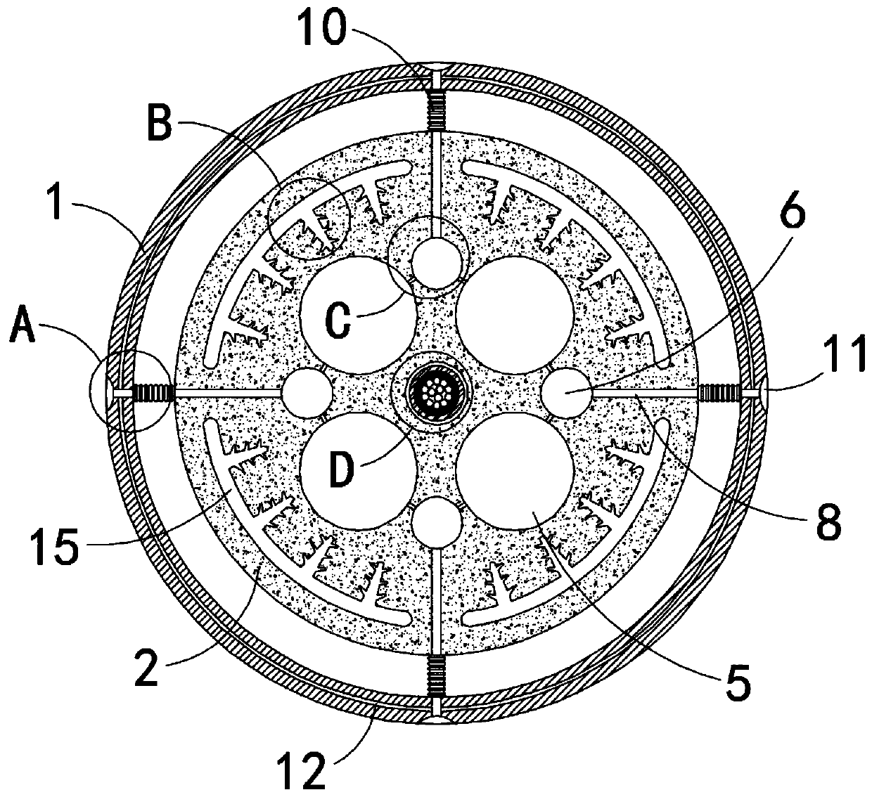
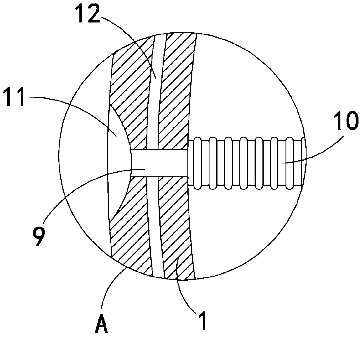
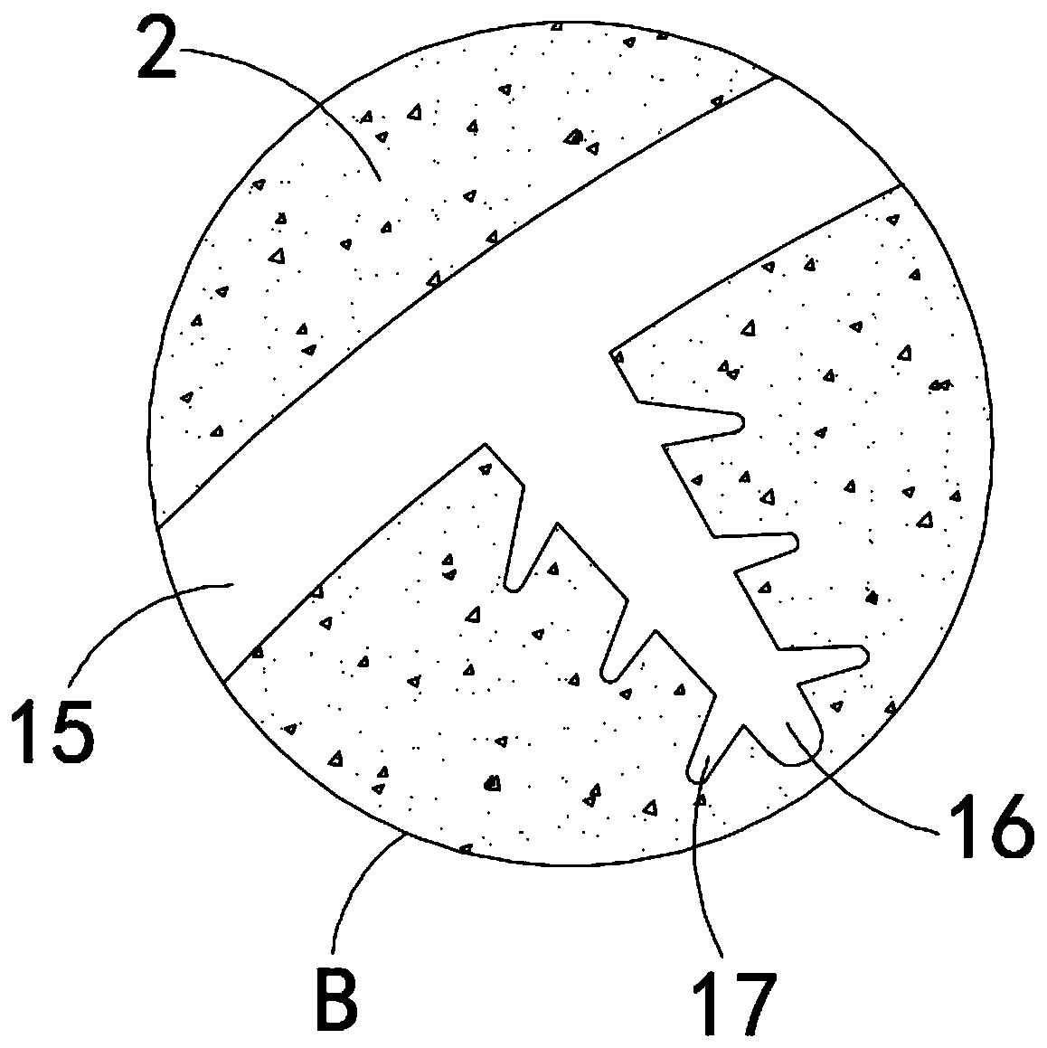
[0031] Such as Figure 1-7 As shown, a multi-channel optical cable bundle tube includes a protective cover 1, and a solid cylindrical body 2 is arranged inside the protective cover 1. Both the protective cover 1 and the solid cylindrical body 2 can be made of rubber, and the center of the solid cylindrical body 2 is along its A reinforcement cavity 3 is provided in the axial direction, and the reinforcement cavity 3 is arranged coaxially with the columnar body 2. A tensile tube 4 is provided in the reinforcement cavity 3. The outer wall of the tensile tube 4 is in contact with the inner wall of the reinforcement cavity 3, and the reinforcement cavity 3 is reinforced. A plurality of optical cable placement cavities 5 are evenly distributed around the cavity 3, and the plurality of optical cable placement cavities 5 take the reinforcement cavity 3 as a uniform part of the center. An infusion channel 7 communicates with the optical cable placement cavity 5, the diameter of the in...

Embodiment 2

[0042] Such as Figure 8 As shown, the difference between this embodiment and Embodiment 1 is that the gap between the solid columnar body 2 and the protective cover 1 is filled with a non-Newtonian liquid 18, and the non-Newtonian liquid 18 is a fluid that does not satisfy a linear relationship. It has the characteristics of "when you meet the strong, you are strong, and when you meet the weak, you are weak".

[0043] By filling the gap between the solid cylindrical body 2 and the protective sheath 1 with a non-Newtonian liquid 18, when the optical cable is hit or beaten by an external force, it will produce a relatively strong hardness and improve the compression and impact resistance of the bundle tube. The cluster tubes play a protective role.


PUM

PropertyMeasurementUnit
diameteraaaaaaaaaa

Abstract

The invention belongs to the field of bundle tubes, and in particular relates to a multi-channel optical cable bundle tube, which includes a protective cover, a solid columnar body is arranged inside the protective cover, and a reinforcement cavity is arranged at the center of the solid columnar body along its axial direction. There is a tensile tube, and there are multiple optical cable placement cavities evenly distributed around the reinforcement cavity. There is a lubrication cavity between two adjacent optical cable storage cavities. The lubrication cavity is connected with the optical cable storage cavity through multiple infusion channels. There is a lubricant used to reduce the friction between the optical cable and the cavity where the optical cable is placed. A reinforcement tube is fixedly connected to the side wall of the lubrication cavity away from the reinforcement cavity. The other end of the reinforcement tube penetrates radially to the outside along the solid cylindrical body. On the protective cover A connecting pipe corresponding to the position of the reinforcing pipe is provided. The invention can overflow the lubricant in the whole process by setting the lubricating cavity, reduce the friction force between the optical cable and the optical cable placement cavity, increase the conveying distance, and thus improve the laying efficiency.

Description

technical field [0001] The invention belongs to the field of bundle tubes, in particular to a multi-channel optical cable bundle tube. Background technique [0002] Optical cable is a special cable made of optical fiber and used for communication signal transmission. [0003] During the laying process of optical cables, the optical cable air blowing method is usually used, that is, the optical cable is blown into the pre-embedded silicon core tube by high-pressure air blowing, in order to reduce the friction between the optical cable and the pipe, thereby prolonging the transportation of the optical cable The staff usually inject lubricant into the pipeline, but due to the limited depth of manual injection of lubricant, it will cause uneven distribution of lubricant in the pipeline, so that the optical cable is no longer lubricated when it is transported to the second half The effect affects the laying of optical cables. [0004] In addition, due to the large air pressure ...

Claims


Application Information

Patent Timeline
Patent Type & Authority Patents(China)
IPC IPC(8): G02B6/44
CPCG02B6/50
Inventor 李淑红王朝
Owner 武汉齐力得管业有限公司
Why Eureka
Try Eureka