Assembled rotating shaft

An assembled and rotating shaft technology, applied in the field of mechanical parts, can solve problems such as shortening the service life of rotating shafts, reducing work reliability, and increasing manufacturing costs, and achieves the effects of ensuring transmission strength, reasonable structural design, and low production costs

Inactive Publication Date: 2013-12-04
WUHU FORCE MOLD PARTS
View PDF9 Cites 1 Cited by
  • Summary
  • Abstract
  • Description
  • Claims
  • Application Information

AI Technical Summary

Problems solved by technology

[0003] However, the existing rotating shaft has many processing procedures and complex structure, which increases the manufacturing cost, and the rotating shaft is a solid shaft, and the external wire of the motor is connected to the motor from the side of the rotating shaft, so it is difficult to ensure its airtightness, which shortens the service life of the rotating shaft and reduces the working time. reliability
In some special occasions, it is required that the shaft can be installed and applied in a small space, while the traditional shaft has an integrated structure, which cannot be changed in size and is inconvenient to use

Method used


Image

  • Assembled rotating shaft
  • Assembled rotating shaft
  • Assembled rotating shaft

Examples


Embodiment Construction

[0019] The present invention will be further described below in conjunction with specific embodiments.

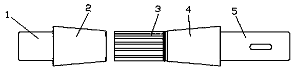
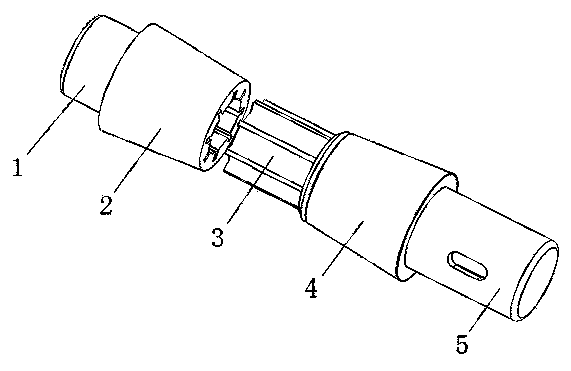
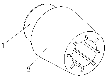
[0020] Such as figure 1 , figure 2 , image 3 , Figure 4 As shown, an assembled shaft includes a shaft head 1 and a shaft tail 5, and also includes an assembled shaft body; the shaft body includes a driven shaft 2 and a driving shaft, and the driven shaft 2 and the shaft head 1 are connected as one, and the driving shaft The shaft and the shaft tail 5 are connected as a whole; the driving shaft includes a joint 3 and a receiving rod 4, and the receiving rod 4 is a circular frustum structure, one end of which is axially connected with one end of the joint 3, and the other end is axially connected with the shaft tail 5; the joint 3 It includes a cylinder 6 and a blade 7; the blade 7 is a cuboid structure, and its bottom end is fixed on the surface of the cylinder 6 vertically in the axial direction; the driven shaft 2 is a circular frustum structure, one end of which is...


PUM

PropertyMeasurementUnit
Heightaaaaaaaaaa
Thicknessaaaaaaaaaa

Abstract

The invention discloses an assembled rotating shaft and belongs to the field of machine parts. The assembled rotating shaft comprises a shaft head and a shaft tail and further comprises an assembled shaft body, wherein the shaft body comprises a driven shaft and a drive shaft; the drive shaft comprises a connector and a bearing rod; the bearing rod adopts a circular truncated cone structure; one end of the bearing rod is axially connected with one end of the connector; the other end of the bearing rod is axially connected with the shaft tail; the connector comprises a cylinder and blades; the blades adopt cuboid structures; the bottom ends of the blades are axially and perpendicularly fixed on the surface of the cylinder; the driven shaft adopts a circular truncated cone structure; one end of the driven shaft is axially connected with the shaft head; a cavity is formed in the other end of the driven shaft; the shape of the cavity is matched with that of the cross section of the connector; a circular ring bulge with a conoid cross section is arranged at the joint of the connector and the bearing rod; the area of cross section of the connector is smaller than that of the bearing rod. The assembled rotating shaft is reasonable in structural design, low in manufacturing cost and convenient to mount.

Description

technical field [0001] The invention belongs to the field of mechanical parts, and more specifically relates to an assembled rotating shaft. Background technique [0002] The rotating shaft is a mechanical component used to transmit torque. Its input end is connected to a power source such as a motor, receives the rotating torque generated by the power source, and transmits the rotating torque to a rotating device such as a gear connected to the output end of the rotating shaft through the torsional deformation of the rotating shaft itself. , to drive the rotating device to rotate. In order to transmit high torque, the diameter of the shaft needs to be large. For example: Chinese Patent No. 201220289028.8, published on January 30, 2013, discloses a patent document named a rotating shaft. The utility model provides a rotating shaft, the rotating shaft includes a main body, and The first cylinder and the second cylinder extending from one end of the body, the main body, the ...

Claims


Application Information

Patent Timeline
IPC IPC(8): F16C3/02
Inventor 李广辉胡玉龙
Owner WUHU FORCE MOLD PARTS
Why Eureka
Try Eureka