
Auxiliary device for form stripping of pervious concrete test block and form stripping method

A technology of permeable concrete and auxiliary device, which is applied in the directions of measuring device, preparation and sampling of test samples, can solve problems such as difficulty in demoulding of permeable concrete test blocks, and achieve the effect of quick demoulding and eliminating adhesion.

Pending Publication Date: 2018-05-08
四川中核艾瑞特工程检测有限公司 +1
View PDF8 Cites 0 Cited by
  • Summary
  • Abstract
  • Description
  • Claims
  • Application Information

AI Technical Summary

Problems solved by technology

[0005] Aiming at the above-mentioned problem that it is necessary to invent an auxiliary device to solve the problem of difficult demoulding of permeable concrete test blocks and to establish a solid foundation for the efficient work of the laboratory, the present invention provides a permeable concrete test block for demoulding. Auxiliary device and method for removing formwork, using the auxiliary device and method for removing formwork, compressed air can be used to efficiently remove formwork for permeable concrete

Method used


Image

  • Auxiliary device for form stripping of pervious concrete test block and form stripping method

Examples


Embodiment 1

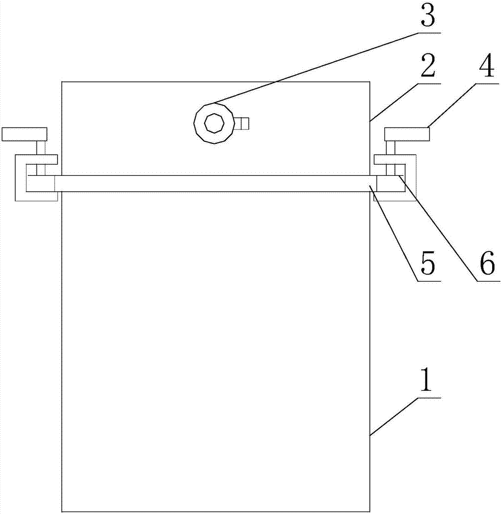
[0036] Such as figure 1 As shown, an auxiliary device for removing the formwork of a permeable concrete test block, including a cover body 2, a sealing strip 5 and a connecting device 4;

[0037] The cover 2 is a box-like structure with an opening at the lower end;

[0038] The opening at the lower end of the cover body 2 is used to dock with the opening at the upper end of the test mold 1, and the sealing strip 5 is annular, and the sealing strip 5 is used as a seal between the above two openings;

[0039] The connecting device 4 is used as a connecting piece between the cover body 2 and the test mold 1 when the above two openings are docked.

[0040] Permeable concrete is different from traditional concrete. Because of the pores between its aggregates, when demolding pervious concrete test blocks, it is impossible to use an air compressor to demolish pervious concrete like ordinary concrete: ordinary concrete is demolished using an air compressor. The principle of the mold i...

Embodiment 2

[0046] Such as figure 1 As shown, this embodiment is further limited on the basis of embodiment 1: after the demoulding is completed by compressed air, in order to realize the rapid pressure relief of the connecting body, it also includes a pressure relief valve arranged on the cover body 2 The pressure relief hole communicates with the inner and outer sides of the cover body 2, and the pressure relief hole is used to connect the pressure relief valve 3. In this solution, a pressure relief hole is provided on the cover body 2, and the pressure relief hole can also be used to repeatedly inflate and deflate the connecting body, so that the permeable concrete and Separation of trial mold 1. The above method of repeatedly inflating and deflating the connecting body is especially suitable for the working conditions where the test mold 1 has a small amount of expansion when it is subjected to internal pressure, such as the test mold 1 is a metal test mold 1, or the test mold 1 itse...


PUM


Abstract

The invention discloses an auxiliary device for form stripping of a pervious concrete test block and a form stripping method. The auxiliary device comprises a cover body, a sealing strip and connecting devices, wherein the cover body is of a box body-shaped structure of which the lower end is provided with an opening; the opening in the lower end of the cover body is used for butting against an opening in the upper end of a test mold; the sealing strip is annular and is used as a sealing element between the two openings; the connecting devices are used as connectors between the cover body andthe test mold when the two openings are butted. The method comprises the following steps: closing the upper end of the test mold; introducing compressed gas into the test mold and separating the testmold from the test block after the test mold expands. According to the auxiliary device and the method, efficient form stripping of the pervious concrete test block can be realized by using compressedair.

Description

technical field [0001] The invention relates to the technical field of concrete engineering detection equipment, in particular to an auxiliary device and a form removal method for a permeable concrete test block form removal. Background technique [0002] Since the country put forward the concept of building a sponge city, permeable concrete pavement has been used more and more all over the country. In the industry standard "Technical Regulations for Permeable Cement Concrete Pavement" CJJ / T135-2009, it is clearly stated that every 100m of paving 3 For permeable concrete with the same ratio, a set of compression test pieces and a set of flexural test pieces shall be formed, each 500m 3 Sampling test a group of test pieces for water permeability coefficient. At the same time, when designing the mix ratio of permeable concrete in the laboratory, it is also necessary to form a large number of test pieces for compression resistance, flexural resistance, and water permeability c...

Claims


Application Information

Patent Timeline
IPC IPC(8): G01N1/36
CPCG01N1/36G01N2001/366
Inventor 徐高友张辉赤张建平刘学良沈媛媛曾莉媛韩桂琴
Owner 四川中核艾瑞特工程检测有限公司
Learn More