

Substation site lightning impulse and oscillation lightning impulse voltage test device
A technology of lightning impulse voltage and impulse voltage is applied in the field of lightning impulse and oscillating lightning impulse voltage test devices in substations. , the effect of low cost
Active Publication Date: 2018-05-08
STATE GRID CORP OF CHINA +3
View PDF2 Cites 7 Cited by
- Summary
- Abstract
- Description
- Claims
- Application Information
AI Technical Summary
Problems solved by technology
[0003] In the prior art, the lightning impulse voltage and the oscillating lightning impulse voltage need to be independently generated by two sets of test devices; when conducting handover acceptance tests on site or conducting comparative research on insulation characteristics in the laboratory, it is also necessary to build two sets of test devices. The test workload is heavy, the test procedure is complicated, and the equipment cost is high
Method used
View moreImage
Smart ImageViewing Examples

Examples
Embodiment 1
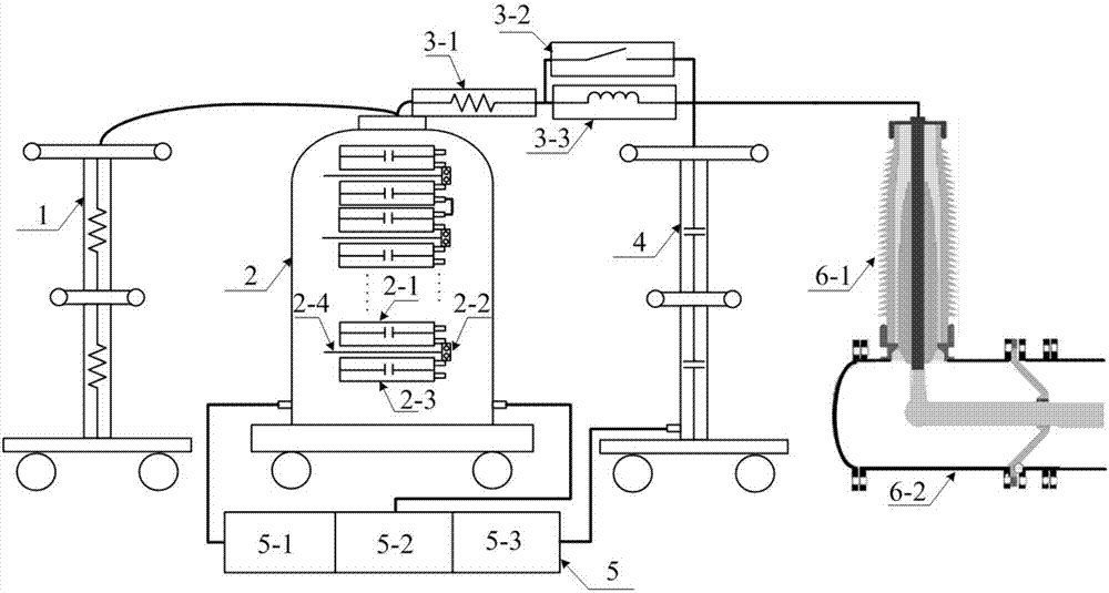
[0045] In practical application, refer to figure 1 , the test device for lightning impulse and oscillating lightning impulse voltage includes: 3MV SF 6 Gas-insulated impulse voltage generator, 100Ω wave head resistor, 1kΩ wave tail resistor, wave head inductor, SF 6 Insulated diverter switch, 3MV impact voltage divider and GIS test product.
Login to View More PUM
 Abstract
The invention discloses a substation site lightning impulse and oscillation lightning impulse voltage test device which includes an impulse voltage generator, a wave front resistor, a wave front inductor, a wave tail resistor, a change-over switch and an impulse voltage measurement and control system. The high-voltage end of the impulse voltage generator is connected with one end of the wave tailresistor and one end of the wave front resistor. The other end of the wave tail resistor is grounded. The other end of the wave front resistor is connected with one end of the wave front inductor andone end of the change-over switch. The other end of the wave front inductor is connected with the other end of the change-over switch to form an output end. The impulse voltage measurement and controlsystem is used for controlling the charging and triggering of the impulse voltage generator. Both a lightning impulse voltage and an oscillation lightning impulse voltage can be generated. Interactive generation of a lightning impulse voltage and an oscillation lightning impulse voltage can be realized by switching the elements of the test circuit only. The operation is convenient, and the cost of equipment is low.
Description
technical field [0001] The invention belongs to the technical field of impulse voltage generation, and in particular relates to a lightning impulse and oscillation lightning impulse voltage test device at a substation site. Background technique [0002] When handing over and accepting GIS (gas-insulated metal-enclosed switchgear) at the substation site, in addition to the AC withstand voltage test, it is also necessary to use lightning impulse or oscillating lightning impulse as an auxiliary voltage to test the insulation characteristics of the equipment. For example, on-site insulation characteristic testing for GIS busbars and insulators. [0003] In the prior art, the lightning impulse voltage and the oscillating lightning impulse voltage need to be independently generated by two sets of test devices; when conducting handover acceptance tests on site or conducting comparative research on insulation characteristics in the laboratory, it is also necessary to build two sets ...
Claims
Login to View More Application Information
Patent Timeline
 IPC IPC(8): G01R31/12
CPCG01R31/1254
Inventor张璐孙强韩彦华王勇王森孙蕾褚磊张乔根毛辰尚宇王辰曦惠华
OwnerSTATE GRID CORP OF CHINA