
Manufacturing method of switch power supply housing

A technology of switching power supply and manufacturing method, which is applied in the direction of modification of power electronics, electrical components, output power conversion devices, etc., can solve problems such as circuit board layout limitations, achieve reduction of complicated processes, save manufacturing costs, and simplify manufacturing processes Effect

Active Publication Date: 2018-05-08
JIANGSU UNIV OF TECH
View PDF3 Cites 0 Cited by
  • Summary
  • Abstract
  • Description
  • Claims
  • Application Information

AI Technical Summary

Problems solved by technology

The current switching power supply generally adopts an L-shaped base and a cover connected together up and down to form an overall rectangular shell-shaped shell, and the L-shaped base and cover must be connected together up and down in the manufacturing process. When it is necessary to increase the bending process to form the connecting plate part for connection, such as forming the socket part for connection through the bending process, then the L-shaped base and cover body need at least the second step during manufacture. The basic shape of the L shape is formed once, the plugging part is formed for the second time, and the fixed connection part is formed for the third time, a total of three times of bending, and the L-shaped base and cover will also limit the layout of the circuit board. For the base The connection with the cover body is fixed, and the space occupied by electronic components needs to be considered when planning the circuit layout of the circuit board

Method used


Image

  • Manufacturing method of switch power supply housing
  • Manufacturing method of switch power supply housing
  • Manufacturing method of switch power supply housing

Examples


Embodiment 1

[0055] (Embodiment 1. Shell of switching power supply)

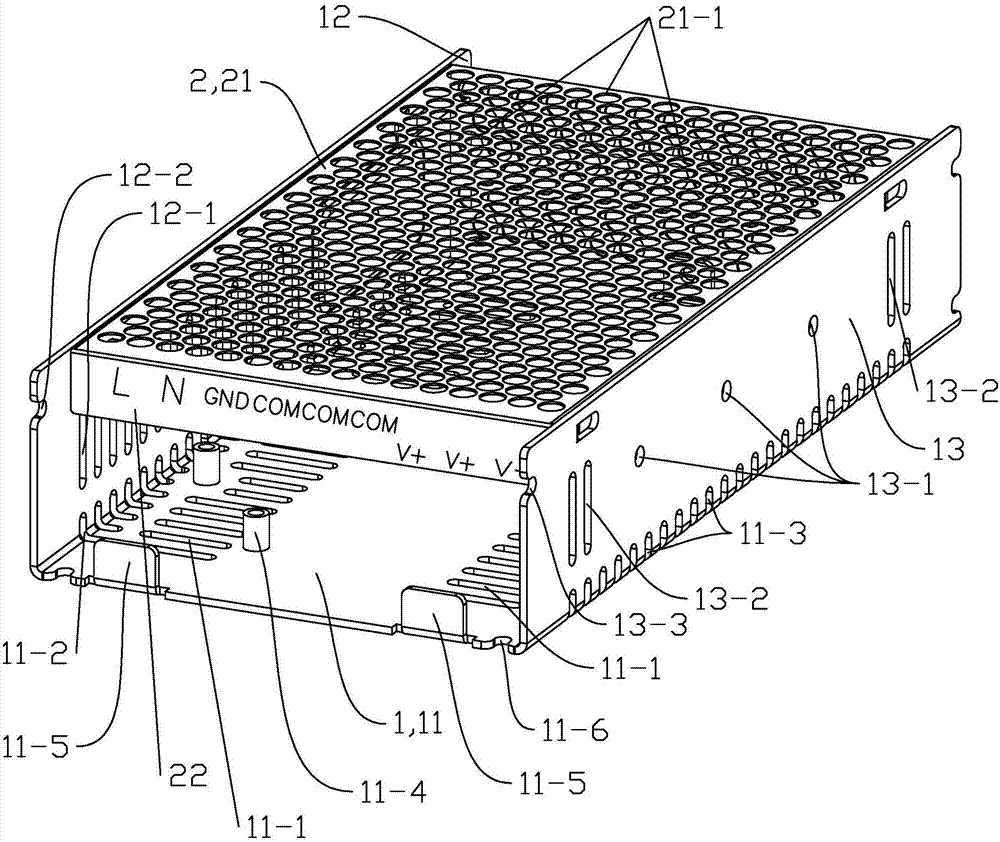
[0056] see figure 1 The housing of the switching power supply of this embodiment includes a base 1, a cover 2 detachably mounted on the base 1, and a connecting screw that fixes the base 1 and the cover 2 together. Both the base 1 and the cover 2 are stamped parts made of aluminum or steel.

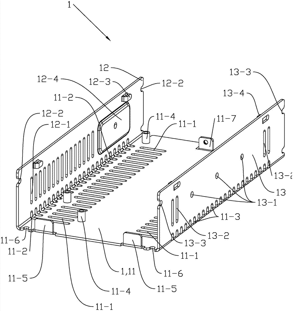
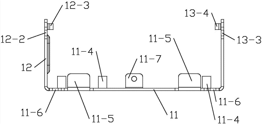
[0057] see Figure 2 to Figure 5 , The base 1 is U-shaped as a whole, including a bottom plate 11, a left side plate 12 and a right side plate 13. The bottom plate 11 is arranged horizontally; the left side plate 12 is arranged vertically and connected to the left end of the bottom plate 11 from above; the right side plate 13 is vertical It is connected to the right end of the bottom plate 11 from above. The left and right sides of the bottom plate 11 are symmetrically provided with first heat dissipation holes 11-1 distributed at equal intervals along the axial direction, and the first heat dissipation holes 11-1 have a waist shape. T...

Embodiment 2

[0061] (Embodiment 2. Manufacturing method of the housing of the switching power supply)

[0062] The manufacturing method of the shell of the switching power supply obtained in Example 1 respectively includes the manufacturing method of the base 1 and the manufacturing method of the cover 2. The manufacturing method of the base 1 includes the following steps:

[0063] ①See Picture 10 , The preliminary shape of the base 1 is formed by blanking and punching using a progressive die process: the first heat dissipation hole 11-1, the second heat dissipation hole 11-2, the third heat dissipation hole 11-3, and the first limit hole 11 of the bottom plate 11 -6. The screw holes on the circuit board blocking plate 11-5, the connecting plate 11-7 and the connecting plate 11-7, and the mounting holes of the riveting stud 11-4 have been formed, and the mounting part 12-4 of the left side plate 12 , The second limiting hole 12-2 and the left connecting leg 12-3 have been formed, the connectin...


PUM


Abstract

The invention relates to a manufacturing method of a switch power supply housing. The switch power supply housing comprises a base and a cover which is detachably mounted on the base. The base is integrally U-shaped and comprises a base board, a left side board and a right side board. The base board is horizontally arranged. The left side board is vertically arranged and is connected with the leftend of the base board from the upper part. The right side board is vertically arranged and is connected with the right end of the base board from the upper part. The cover is integrally U-shaped andcomprises a top board, a front side board and a back side board. The top board is horizontally arranged. The front side board is vertically arranged and is connected with the front end of the top board from the lower part. The back side board is vertically arranged and is connected with the back end of the top board from the lower part. The base and the cover are provided with heat radiating holesand various mounting holes. The cover is detachably connected with a connecting board between the back side board and the base board of the base through a fastener. The main components of the base and the cover can be formed through one-time bending after punching and material falling. Under a precondition that high heat radiation effect is ensured, machining processes are remarkably reduced.

Description

[0001] This application is a divisional application of the application number: 201510096124.9, the name of the invention and creation is "Switching power supply enclosure and its manufacturing method", and the filing date is: March 4, 2015. Technical field [0002] The invention relates to a shell of a switching power supply formed by stamping and a manufacturing method thereof. Background technique [0003] With the rapid development of power electronic technology, the relationship between power electronic equipment and people’s work and life has become increasingly close, and electronic equipment is inseparable from reliable power supplies. In the 1980s, computer power supplies fully realized switching power supplies, and took the lead in completing computer Switching power supplies have entered various electronic and electrical equipment fields in the 1990s. Switching power supplies have been widely used in program-controlled switches, communications, electronic testing equipmen...

Claims


Application Information

Patent Timeline
Patent Type & Authority Applications(China)
IPC IPC(8): H02M1/00H05K7/20
CPCH02M1/00H05K7/2089
Inventor 臧海娟
Owner JIANGSU UNIV OF TECH
Features
  • Generate Ideas
  • Intellectual Property
  • Life Sciences
  • Materials
  • Tech Scout
  • Unparalleled Data Quality
  • Higher Quality Content
  • 60% Fewer Hallucinations
Learn More