
FPGA-based tracking type resolver decoding circuit

A resolver decoding and tracking technology, applied in electronic commutators and other directions, can solve the problems of large space occupation of printed boards, reduced system reliability, and increased hardware cost of hardware circuits, and achieves improved integration and simple structure. , compact design effect

Inactive Publication Date: 2018-05-08
GUIZHOU AEROSPACE LINQUAN MOTOR CO LTD
View PDF4 Cites 0 Cited by
  • Summary
  • Abstract
  • Description
  • Claims
  • Application Information

AI Technical Summary

Problems solved by technology

The traditional resolver unit mainly uses the AD2S1210 decoding chip as a coprocessor, and the main control chip controls the AD2S1210 and directly reads the solved data. This method takes up a lot of space on the limited printed board, and Increased hardware circuit increases hardware cost and reduces system reliability

Method used


Image

  • FPGA-based tracking type resolver decoding circuit
  • FPGA-based tracking type resolver decoding circuit
  • FPGA-based tracking type resolver decoding circuit

Examples


Embodiment 1

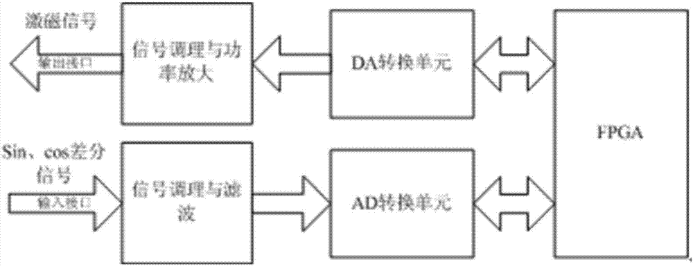
[0067] As mentioned above, the resolver decoding circuit first needs to generate an excitation signal to provide a carrier for the resolver. The original excitation signal is generated by the FPGA software as a digital sine wave sequence with a frequency of 5KHz and adjustable amplitude. The sequence passes through the DA conversion unit Convert it into the original analog signal, and adjust the peak-to-peak value of the sine wave to 3.6V through repeated adjustments. Further, the DA conversion module uses the MAX531DA chip as the core. The chip has a maximum conversion frequency of 1MHz and can meet the frequency requirements of the excitation signal. It can convert 14-bit digital quantity to meet the accuracy requirement of converting analog quantity. From the perspective of the level interface, the digital interface is compatible with 3.3VTTL level and can be directly connected to the FPGA chip; the output signal of the analog output interface is based on 2.5V and the range ...

Embodiment 2

[0069] As mentioned above, the limited rotation angle motor is selected, the rated speed of the motor is 1500rpm, the rated current is 3A, and the power is 100W, and the direct drive method is used for servo. Using the present invention, the test is carried out, and the test results are as follows: Figure 10 and Figure 11 As shown, it can be obtained from the analysis of the position data and the drawn curve that the performance of the solution circuit is stable, and the accuracy can reach the axis angle of 0.02°.


PUM


Abstract

The invention provides an FPGA-based tracking type resolver decoding circuit including an FPGA module, a DA conversion module, a signal adjustment and power amplification module, an AD conversion module, and a signal adjustment and filtering module. The FPGA-based tracking type resolver decoding circuit is characterized in that the FPGA module is connected with the DA conversion module and the ADconversion module, separately, the DA conversion module is connected with the signal adjustment and power amplification module, and the AD conversion module is connected with the signal adjustment andfiltering module. In the invention, the tracking type resolver decoding circuit is designed with an FPGA main control chip as the core, has high tracking accuracy and fast response, and can replace ahardware decoding function module with the AD2S1210 as the core. As compared with a resolver resolving function module of a conventional dedicated decoding chip, the tracking type resolver decoding circuit has a reduced volume by about 50% and an improved degree of integration, the entire controller design is very compact, the resolver tracking accuracy remains unchanged, the direct drive is usedfor servo, the angular position accuracy can reach 0.02 degree, the structure is simple, the control circuit is flexible, the integration degree and servo precision are high, and the expected performance index requirement is met.

Description

technical field [0001] The invention relates to an FPGA-based tracking type resolver decoding circuit, which belongs to the field of high-precision position servo control, and is suitable for a resolver function unit of a position servo control system using a resolver as a position and feedback element. Background technique [0002] The resolver is a position measurement device with high precision, wide temperature range, excellent anti-vibration performance, and can work reliably in harsh environments, so it is widely used in servo systems or adjustments operating under harsh conditions. speed system. The traditional resolver unit mainly uses the AD2S1210 decoding chip as a coprocessor, and the main control chip controls the AD2S1210 and directly reads the solved data. This method takes up a lot of space on the limited printed board, and The increased hardware circuit increases the hardware cost and reduces the reliability of the system. Contents of the invention [000...

Claims


Application Information

Patent Timeline
Patent Type & Authority Applications(China)
IPC IPC(8): H02P6/16
CPCH02P6/16
Inventor 魏旭来李海波汤胜林
Owner GUIZHOU AEROSPACE LINQUAN MOTOR CO LTD
Learn More