Blowing flow distributing device for double-roller thin-strip continuous casting

A twin-roll thin strip continuous casting and air distribution technology, which is applied in the field of iron and steel metallurgy, can solve the problems of increasing the installation difficulty of the tundish, adding additional transportation links for equipment, increasing liquid level fluctuations, etc., to improve stability and strip quality , reduce the amount of steel and the flow rate of molten steel, and increase the effect of activity

Active Publication Date: 2018-05-11
BAOSHAN IRON & STEEL CO LTD
View PDF13 Cites 11 Cited by
  • Summary
  • Abstract
  • Description
  • Claims
  • Application Information

AI Technical Summary

Problems solved by technology

[0008] 1) The structure is many and complex, which increases the additional transportation link of the equipment;
[0009] 2) The increase of the intermediate transition package will increase the difficulty of its installation, and it needs to be equipped with another mechanism during take-off and landing;
[0010] 3) Since the molten steel directly falls into the flow distributor below through the narrow slit, the fluctuation inside the flow distributor caused by the excessive drop is also large, and there is no effect of smoothing the turbulence
[0017] However, the flow distributor still has disadvantages: while supplying molten steel near the side sealing plate, the fluctuation of the liquid level there is increased, which is easy to affect the solidification quality of the strip steel
[0020] The advantages and disadvantages of this design are also obvious: the form is simple, the cost is low, but the fluctuation and solidification uniformity are difficult to control

Method used


Image

  • Blowing flow distributing device for double-roller thin-strip continuous casting
  • Blowing flow distributing device for double-roller thin-strip continuous casting
  • Blowing flow distributing device for double-roller thin-strip continuous casting

Examples


Embodiment 1

[0057] The casting speed of the thin strip is 35m / min, and the distance between the distributor and the gap of the crystallization roller is 35mm.

[0058] The main structural parameters of the blowing air distribution device for twin-roll thin strip continuous casting of the present invention are as follows:

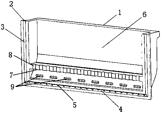
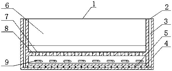
[0059] The distance between the molten steel separator 7 and the molten steel spit hole group 9 is 50mm, and the molten steel separator is provided with 10 circular molten steel falling holes with a diameter of 30mm;

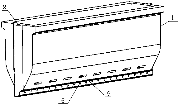
[0060] The number of spit holes in the molten steel spit hole group 9 is 3, and the distance from the bottom of the distributor body 1 is 50mm;

[0061] The number of air outlet holes in air outlet group 5 is 20, and the distance from the bottom of the distributor body is 30 mm.

Embodiment 2

[0063] The casting speed of the thin strip is 60m / min, and the distance between the flow distributor and the gap of the crystallization roller is 68mm.

[0064] The main structural parameters of the blowing air distribution device for twin-roll thin strip continuous casting of the present invention are as follows:

[0065] The distance between the molten steel separator 7 and the molten steel spit hole group 9 is 60 mm, and the molten steel separator is provided with 12 circular molten steel falling holes with a diameter of 25 mm;

[0066] The number of spit holes in the molten steel spit hole group 9 is 2, and the distance from the bottom of the distributor body 1 is 50mm;

[0067] The air outlet hole group 5 has 15 air outlet holes, and the distance from the bottom end of the distributor body is 25mm.

Embodiment 3

[0069] The casting speed of the thin strip is 90m / min, and the distance between the distributor and the gap of the crystallization roller is 77mm.

[0070] The main structural parameters of the blowing air distribution device for twin-roll thin strip continuous casting of the present invention are as follows:

[0071] The distance between the molten steel separator 7 and the molten steel spit hole group 9 is 45mm, and the molten steel separator is provided with 15 circular molten steel falling holes with a diameter of 20mm;

[0072] The number of spit holes in the molten steel spit hole group 9 is 4, and the distance from the bottom of the distributor body 1 is 55mm;

[0073] The number of air outlet holes in the air outlet group 5 is 13, and the distance from the bottom end of the distributor body is 20mm.

[0074] In the air blowing flow distribution device for twin-roll thin strip continuous casting of the present invention, the addition of the molten steel partition insid...


PUM

PropertyMeasurementUnit
diameteraaaaaaaaaa

Abstract

The invention discloses a blowing flow distributing device for double-roller thin-strip continuous casting. The blowing flow distributing device comprises a groove-shaped flow distributor body; air inlets are formed in the two ends of the flow distributor body; channels formed in the air inlets form vertical air inlet channels and a bottom air inlet channel; an air outlet group is formed in the bottom air inlet channel; the flow distributor body is internally provided with a steel liquid containing chamber, and the molten steel containing chamber is provided with a molten steel partition plateso as to form an upper molten steel containing chamber body and a lower molten steel containing chamber body; a molten steel falling hole group is formed in the molten steel partition plate; and a molten steel tapping hole group is formed in the wall surface of the lower molten steel containing chamber body located at the lower part of the molten steel partition plate. According to the blowing flow distributing device, non-uniform flowing of outlet waterflow can be effectively buffered, the tapping amount of tapping holes and the flow rate of molten steel can be effectively decreased, so thatthe high-temperature molten steel can be provide heat for a triangular molten bath from the lower part, the molten steel flowing out of the molten steel tapping holes can be drive to form an upward floating effect and promote upward floating of molten steel inclusions of the molten bath with the coordination of inert gas, the activity degree of the surface of the molten bath can be increased, cold steel membranes can be reduced, and the thin-strip continuous casting stability and the thin-strip quality can be improved.

Description

technical field [0001] The invention relates to iron and steel metallurgy technology, in particular to an air blowing type molten steel distribution device applied to twin-roll strip continuous casting. Background technique [0002] Twin-roll strip continuous casting refers to a production process in which two casting rolls with opposite rotation directions are used as crystallizers to directly introduce liquid metal to produce thin strip steel with a thickness of less than 10mm. Compared with the traditional strip production process, the twin-roll thin strip continuous casting process has the advantages of shortening the process flow, saving energy, reducing production costs and improving the mechanical properties of the strip. Therefore, this technology is considered to be the most promising near-term development in the 21st century. One of the final shape continuous casting technologies. [0003] However, the thin strip continuous casting process in the prior art is a ca...

Claims


Application Information

Patent Timeline
Patent Type & Authority Applications(China)
IPC IPC(8): B22D11/103B22D11/117B22D11/06
CPCB22D11/0622B22D11/103B22D11/117
Inventor 任三兵樊俊飞方园
Owner BAOSHAN IRON & STEEL CO LTD
Why Eureka
Try Eureka