
Three-jaw type follower rest special for turning large-pitch threaded rods

A technology with tool rest and large pitch, applied in the field of machining equipment, can solve the problems of increased vibration, large pitch of the screw with large pitch, affecting the machining accuracy and surface quality of the turning thread

Pending Publication Date: 2018-05-11
HARBIN UNIV OF SCI & TECH
View PDF0 Cites 1 Cited by
  • Summary
  • Abstract
  • Description
  • Claims
  • Application Information

AI Technical Summary

Problems solved by technology

[0002] In the actual turning process of a large-pitch threaded screw on an ordinary lathe, due to the large screw pitch and high feed speed, the cutting force increases during the cutting process, and the vibration generated increases significantly, which seriously affects the machining accuracy and surface of the turning thread. quality
[0003] The pitch of the large-pitch threaded screw is relatively large, and it cannot be completed at one time during turning. It needs to be cut in layers in the left and right axial directions, and multiple cuts are required. The traditional tool rest can only be clamped on the outer diameter of the workpiece, and it needs to follow the slide box for many times. Back-and-forth movement, multiple times of friction on the thread surface, the traditional tool rest easily causes great wear to the thread during the movement of the sliding crate, and even causes thread damage, and the support point of the traditional tool rest is in the same plane, So not suitable for clamping screw parts
[0004] The size of the inner diameter of the large-pitch thread is inconsistent with the diameter of the tool relief groove left at the chucking end of the machine tool chuck. If the rack is not withdrawn in time, it will cause damage to the workpiece and the tool rest, resulting in danger

Method used


Image

  • Three-jaw type follower rest special for turning large-pitch threaded rods
  • Three-jaw type follower rest special for turning large-pitch threaded rods
  • Three-jaw type follower rest special for turning large-pitch threaded rods

Examples


Embodiment Construction

[0022] The following is a detailed description of the technical features and usage methods of the present invention in conjunction with the accompanying drawings.

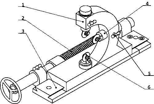
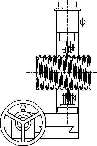
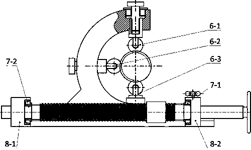
[0023] figure 1 It is a schematic diagram of the overall structure of a special three-jaw heel tool holder for turning large-pitch threaded screws according to the present invention, including a slidable heel tool holder base 3 and a driving device, a semicircular arc-shaped heel tool holder body 1 and an axial axis for centering. Adjustable support claws 6, the slidable heel rest base 3 is installed on the saddle of the machine tool slide box, moves with the slide box, on the slidable heel rest base there is a semicircular arc heel knife The moving track of the frame body is dovetail-shaped, and is precisely matched with the semicircular arc and the tool holder body, so that the semicircular arc and the tool holder body can only move laterally and cannot be separated, so as to achieve stability; On one side of th...


PUM


Abstract

The invention discloses a three-jaw type follower rest special for turning large-pitch threaded rods, and belongs to the field of mechanical machining equipment. The three-jaw type follower rest comprises a semi-arc follower rest body 1, a sliding base driving lead screw 2, a sliding follower rest base 3, a supporting jaw telescopic driving rod 4, axial adjustable supporting jaws 6 and a trapezoidal bearing roller 13. The axial adjustable supporting jaws are arranged in the arc radial direction of the follower rest body, the trapezoidal bearing roller 13 is installed at the centripetal end ofthe follower rest body, in addition, the trapezoidal bearing roller can be adjusted in the axial direction of a workpiece and is of a trapezoidal structure, the axial adjustable supporting jaws can betelescopic in the radial direction, and the semi-arc follower rest body can slide along the sliding follower rest base. According to the three-jaw type follower rest, the machining precision of the large-pitch trapezoidal threaded rods is improved, operation is convenient during use, safety and stability are achieved, and the three-jaw type follower rest is suitable for machining of the large-pitch threaded rods different in diameter and pitch.

Description

technical field [0001] The invention relates to a special three-jaw type heel tool holder for turning large-pitch threaded screws, which belongs to the field of mechanical processing equipment. Background technique [0002] In the actual turning process of a large-pitch threaded screw on an ordinary lathe, due to the large screw pitch and high feed speed, the cutting force increases during the cutting process, and the vibration generated increases significantly, which seriously affects the machining accuracy and surface of the turning thread. quality. [0003] The pitch of the large-pitch threaded screw is relatively large, and it cannot be completed at one time during turning. It needs to be cut in layers in the left and right axial directions, and multiple cuts are required. The traditional tool rest can only be clamped on the outer diameter of the workpiece, and it needs to follow the slide box for many times. Back-and-forth movement, multiple times of friction on the th...

Claims


Application Information

Patent Timeline
IPC IPC(8): B23Q1/76B23G1/44
CPCB23G1/44B23Q1/766
Inventor 李哲王秀瑞李军委李景帅周亚栋
Owner HARBIN UNIV OF SCI & TECH
Learn More