Robot with damping function
A technology of robots and shock absorbers, which is applied in the direction of manipulators, manufacturing tools, program-controlled manipulators, etc., and can solve problems such as low ground flatness and imperfect robot shock absorption systems
- Summary
- Abstract
- Description
- Claims
- Application Information
AI Technical Summary
Problems solved by technology
Method used
Image
Examples
Embodiment 1
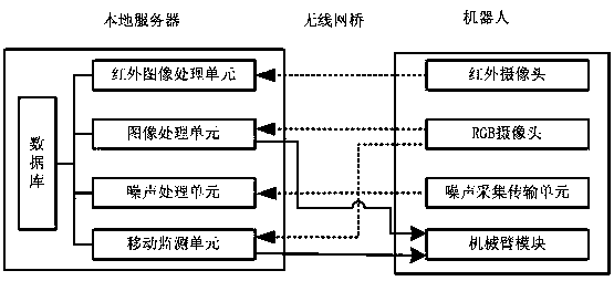
[0031] Such as figure 1 As shown in Fig. 1, a robot-based integrated pipe gallery inspection system is built with the robot as the carrier platform. Of course, different detection systems or devices can be built on this platform.
[0032] The system includes remote infrared monitoring and diagnosis module, remote image monitoring and diagnosis module, remote sound monitoring and diagnosis module, navigation positioning and motion control module, database; remote infrared monitoring and diagnosis module, remote image monitoring and diagnosis module, remote sound monitoring It is connected with the diagnosis module, the navigation positioning module and the motion control module respectively through the network and the database.
[0033] Remote infrared monitoring and diagnosis module
[0034] This design uses an online infrared thermal imaging device. This module includes an infrared image acquisition device, that is, an infrared camera, an infrared image processing unit, an...
Embodiment 2
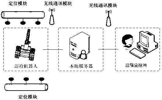
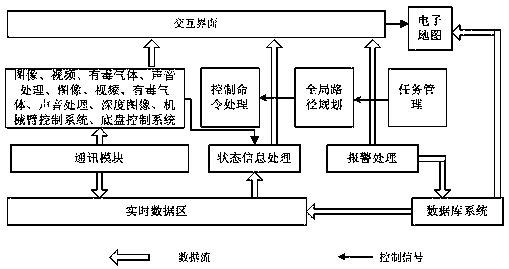
[0048] Such as figure 1 , figure 2 , image 3 As shown, a robot with a shock absorption function includes a patrol inspection system, a robot, a server, and a remote monitoring terminal; the patrol inspection system, the server, and the remote monitoring terminal are connected through a network. The inspection system is the inspection system of the first embodiment above. The infrared camera, RGB camera, and noise acquisition and transmission unit are all installed and fixed on the robot; the server includes a database storing various parameter information of the environment in the underground pipe gallery and electrical equipment; the infrared image processing unit, image processing unit, and noise processing unit will The inspection information is stored in the database; the server sends the inspection information to the remote monitoring terminal through the network; the user queries the inspection information and sends instructions to the inspection system through the r...
Embodiment 3
[0054] Such as Figure 4 , Figure 5 As shown, a shock-absorbing chassis of a robot, the robot includes a chassis system; the specific structure of the chassis system is:
[0055] The motor 1 is connected to the reducer 2, and the motor 1 and the reducer 2 are fixed on the fixed sleeve of the reducer by bolts. The shaft end of the reducer 2 and the fixed sleeve of the reducer are provided with fixing bolts to prevent the driving wheel from falling off due to excessive axial force. , the fixed shaft sleeve of the reducer 2 clamps the driving wheel, the fixed shaft sleeve of the reducer 2 is fixed in the bearing sleeve through the bearing and positioned on the outer fixed plate 3, and the outer fixed plate 3 and the inner fixed plate 4 are connected by three The fixed plate fixes the longitudinal position so that the drive wheels are always driven on the inner teeth of the track. The driving wheel is divided into 2 pieces for the purpose of convenient processing. After the pro...
PUM
 Abstract
Description
Claims
Application Information
 - R&D
- Intellectual Property
- Life Sciences
- Materials
- Tech Scout
- Unparalleled Data Quality
- Higher Quality Content
- 60% Fewer Hallucinations
Browse by: Latest US Patents, China's latest patents, Technical Efficacy Thesaurus, Application Domain, Technology Topic, Popular Technical Reports.
© 2025 PatSnap. All rights reserved.Legal|Privacy policy|Modern Slavery Act Transparency Statement|Sitemap|About US| Contact US: help@patsnap.com


