Cutting device for ceramsite blocks

A cutting device and ceramsite block technology are applied in the direction of stone processing tools, work accessories, manufacturing tools, etc., which can solve the problems of increasing the temperature of the cutting blade and affecting the cutting effect, and achieve the effect of ensuring the cutting effect.

Active Publication Date: 2018-05-11
重庆成维轻质墙板有限公司
View PDF7 Cites 2 Cited by
  • Summary
  • Abstract
  • Description
  • Claims
  • Application Information

AI Technical Summary

Problems solved by technology

[0004] The present invention intends to provide a ceramsite block cutting device to solve the problem that the cutting effect is affected by the temperature rise of the cutting knife when the current ceramsite block cutting device is cutting

Method used


Image

  • Cutting device for ceramsite blocks
  • Cutting device for ceramsite blocks
  • Cutting device for ceramsite blocks

Examples


Embodiment Construction

[0017] Further detailed explanation through specific implementation mode below:

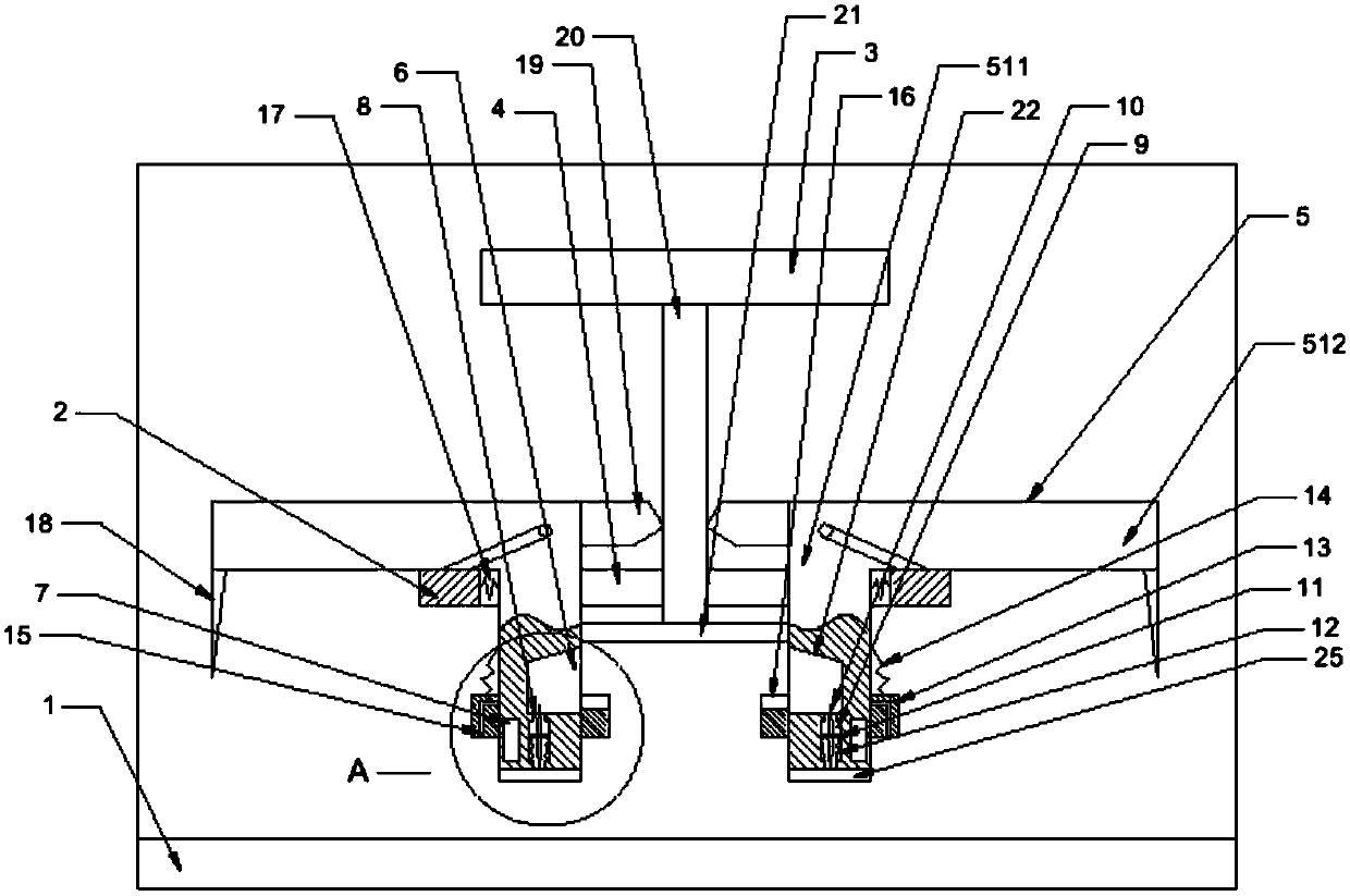
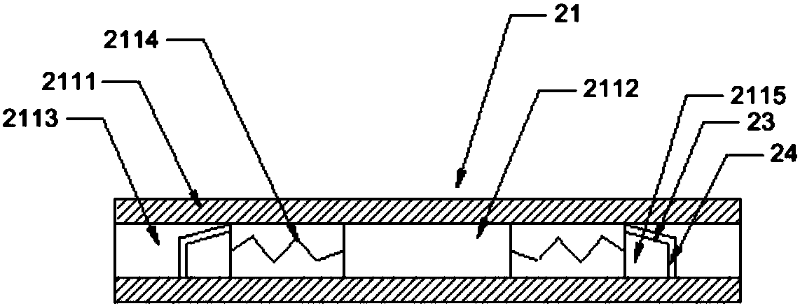
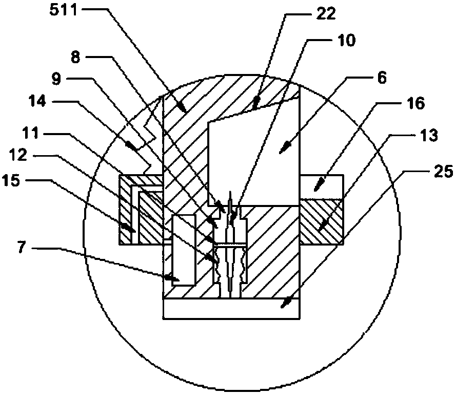
[0018] The reference signs in the drawings of the description include: machine base 1, support frame 2, cylinder 3, through hole 4, L-shaped block 5, vertical section 511, transverse section 512, chute 6, water storage tank 7, knife groove 8 , guide groove 9, cutting knife 10, rotating shaft 11, first spring 12, casing 13, second spring 14, outlet hole 15, auxiliary groove 16, third spring 17, plug 18, protrusion 19, extrusion rod 20. Telescopic plate 21, fixed plate 2111, fixed block 2112, through groove 2113, fourth spring 2114, slide block 2115, first slope 22, second slope 23, rubber layer 24, sponge layer 25.

[0019] The embodiment is basically as attached figure 1 , attached figure 2 And attached image 3 Shown: Ceramsite block cutting device, including machine base 1, on which support frame 2 and cylinder 3 are welded, a through hole 4 is opened in the center of support frame 2, and s...


PUM

PropertyMeasurementUnit
strengthaaaaaaaaaa

Abstract

The invention belongs to the technical field of processing of stones or similar stone materials, and particularly discloses a cutting device for ceramsite blocks. The cutting device comprises a machine base, wherein a supporting frame and an air cylinder are arranged on the machine base, a through hole is formed in the supporting frame, ans L-shaped blocks are symmetrically hinged to the supporting frame; the L-shaped blocks comprise vertical sections and transverse sections, wherein sliding grooves and water storage grooves are arranged on the side walls of the vertical sections, knife grooves are formed in the vertical sections, and guide grooves are formed in the inner walls of the knife grooves; cutting knifes are further arranged in the cutter grooves, rotating shafts are arranged onthe cutting knifes in a penetrating mode, the rotating shafts are in sliding connection with the guide grooves, and first springs are arranged between the rotating shafts and the guide grooves; sleeves are slidably connected to the vertical sections, and second springs are arranged between the sleeves and the vertical sections; water outlet holes are formed in the inner walls of the sleeves, and auxiliary grooves are formed in the outer walls of the sleeves; third springs are arranged between the vertical sections and the inner walls of the through holes; inserting blocks are vertically arranged on the transverse sections; bulges are further arranged on the transverse sections; and an extrusion rod is arranged on the air cylinder, and a telescopic plate is arranged on the extrusion rod. According to the scheme, and the problem that the cutting effect is influenced due to the fact that the temperature of the cutting knifes rises during cutting of an existing cutting device for the ceramsite blocks is mainly solved.

Description

technical field [0001] The invention relates to the technical field of processing stone or stone-like materials, in particular to a ceramsite block cutting device. Background technique [0002] Ceramsite concrete (also ceramsite block) is a new type of wall material made of ceramsite instead of stone as the coarse aggregate of ceramsite block, with cement and fly ash as auxiliary materials, and foamed and stirred by thermal insulation foaming agent. Its thermal insulation and heat resistance are good, and the strength of ceramsite bricks can be greater than 7MPa. The use of ceramsite hollow blocks as wall materials can save labor and materials, reduce the labor intensity of workers, the painting is not hollow, and it is not easy to produce cracks. It has excellent sound insulation and heat insulation performance, convenient decoration, and high firmness. It is an ideal energy-saving building. Self-insulating and energy-saving wall materials. In addition, the ceramsite bloc...

Claims


Application Information

Patent Timeline
Patent Type & Authority Applications(China)
IPC IPC(8): B28D1/24B28D7/00B28D7/02B28D7/04
CPCB28D1/24B28D7/00B28D7/02B28D7/04
Inventor 蒋仁彬
Owner 重庆成维轻质墙板有限公司
Why Eureka
Try Eureka