

Air vehicle with buffering structure and working method
A buffer structure and working method technology, applied in the field of aircraft, can solve the problems of damage to the service life of the aircraft, the inability to adjust the gradient, and insufficient buffer effect, etc., to achieve the effects of extending the service life, improving the buffer effect, and improving the buffer effect
- Summary
- Abstract
- Description
- Claims
- Application Information
AI Technical Summary
Problems solved by technology
Method used
Image

Examples
no. 1 example
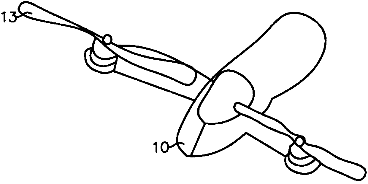
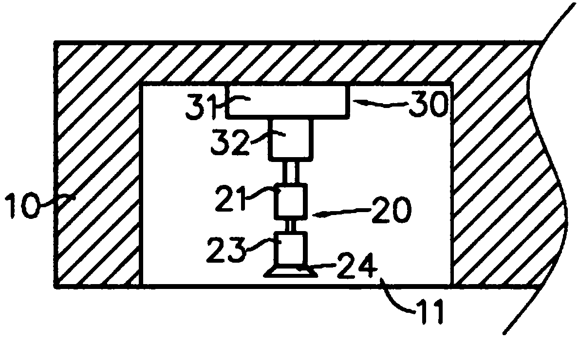
[0035] Such as Figure 1 to Figure 3 As shown, the aircraft with a buffer structure in this embodiment includes a frame 10 , a buffer assembly 20 , and a first push assembly 30 .
[0036] The rack 10 has a receiving slot 11 . The buffer assembly 20 is arranged in the receiving groove 11, the first push assembly 30 is arranged on the frame 10, the first end of the first push assembly 30 is connected with the frame 10, the second end of the first push assembly 30 is connected with the buffer assembly 20 Connected, the first push assembly 30 has a telescopic structure, and the telescopic structure is used to drive the buffer assembly 20 to move.
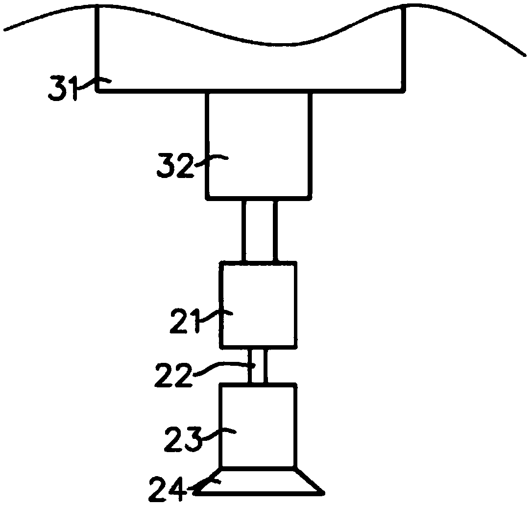
[0037] Specifically, the first push assembly 30 includes a hydraulic assembly 31 and a telescopic structure 32 connected in sequence, and the telescopic structure 32 is connected with the buffer assembly 20 . The buffer assembly 20 includes a first connecting block 21, an elastic member 22, a second connecting block 23 and an elastic ...
no. 2 example
[0048] The aircraft of this embodiment is basically the same as the above-mentioned first embodiment, and only the differences will be described in detail below.
[0049] Such as Figure 4 As shown, the first pushing assembly 30 of this embodiment includes a first motor 41, a driving gear 42, a first driven gear 44, a first connecting rod 45, a second driven gear 46, and a first screw rod 47 connected in sequence. , the first screw rod 47 is connected with the buffer assembly 20 (refer to the first embodiment for the structure), and when the second driven gear 46 rotates, the first screw rod 47 moves along the axis of the second driven gear 46 . The first pushing assembly 30 also includes the third driven gear 51, the second connecting rod 52, the fourth driven gear 53, the second screw mandrel 54 connected in sequence, the second screw mandrel 54 is connected with another buffer assembly 20 (refer to the structure First embodiment) connection, when the fourth driven gear 53 ...
no. 3 example
[0054] The aircraft of this embodiment is basically the same as the above-mentioned first embodiment, and only the differences will be described in detail below.
[0055] The aircraft also includes wings and a power mechanism, the power mechanism is connected with the wings, and the control unit is connected with the power mechanism; the control unit has a comparison module, and the comparison module is used to compare whether the ratio of the pressure detection value of the pressure sensor to the set pressure value exceeds the set pressure value. When the ratio of the pressure detection value to the set pressure value exceeds the set range, the control unit increases the power of the power mechanism.
[0056] The working method of the present embodiment also includes the following steps:
[0057] T1: When the ratio of the pressure detection value of the comparison module comparing the pressure sensor to the set pressure value exceeds the set range, the control unit increases ...
PUM
 Abstract
Description
Claims
Application Information