Gas cooker light-emitting device and gas cooker

A lighting device and gas stove technology, applied in the field of gas stoves, to achieve the effects of saving production costs and simplifying the production process

Active Publication Date: 2018-05-11
QINGDAO HAIER WISDOM KITCHEN APPLIANCE CO LTD
View PDF7 Cites 5 Cited by
  • Summary
  • Abstract
  • Description
  • Claims
  • Application Information

AI Technical Summary

Problems solved by technology

[0005] The object of the present invention is to provide a gas stove lighting device a

Method used


Image

  • Gas cooker light-emitting device and gas cooker
  • Gas cooker light-emitting device and gas cooker
  • Gas cooker light-emitting device and gas cooker

Examples


Embodiment Construction

[0028] The technical solutions of the present invention will be further described below in conjunction with the accompanying drawings and through specific implementation methods.

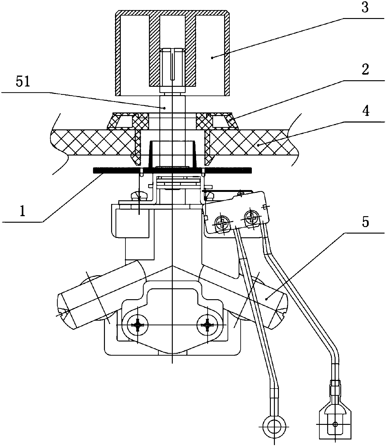
[0029] The invention provides a gas cooker lighting device, which is installed on the gas cooker, such as figure 1 As shown, the gas stove lighting device includes a potentiometer 1, a light ring 2, a knob 3 and a control panel (not shown in the figure), wherein:

[0030] The potentiometer 1 is connected to the control board, which is located under the panel 4 of the gas stove, and is sleeved on the valve stem 51 of the gas valve 5. The potentiometer 1 can rotate with the valve stem 51, and the potentiometer 1 rotates to different positions corresponding to The resistance value is different, and the potentiometer 1 will send its resistance value to the control board in the form of a signal.

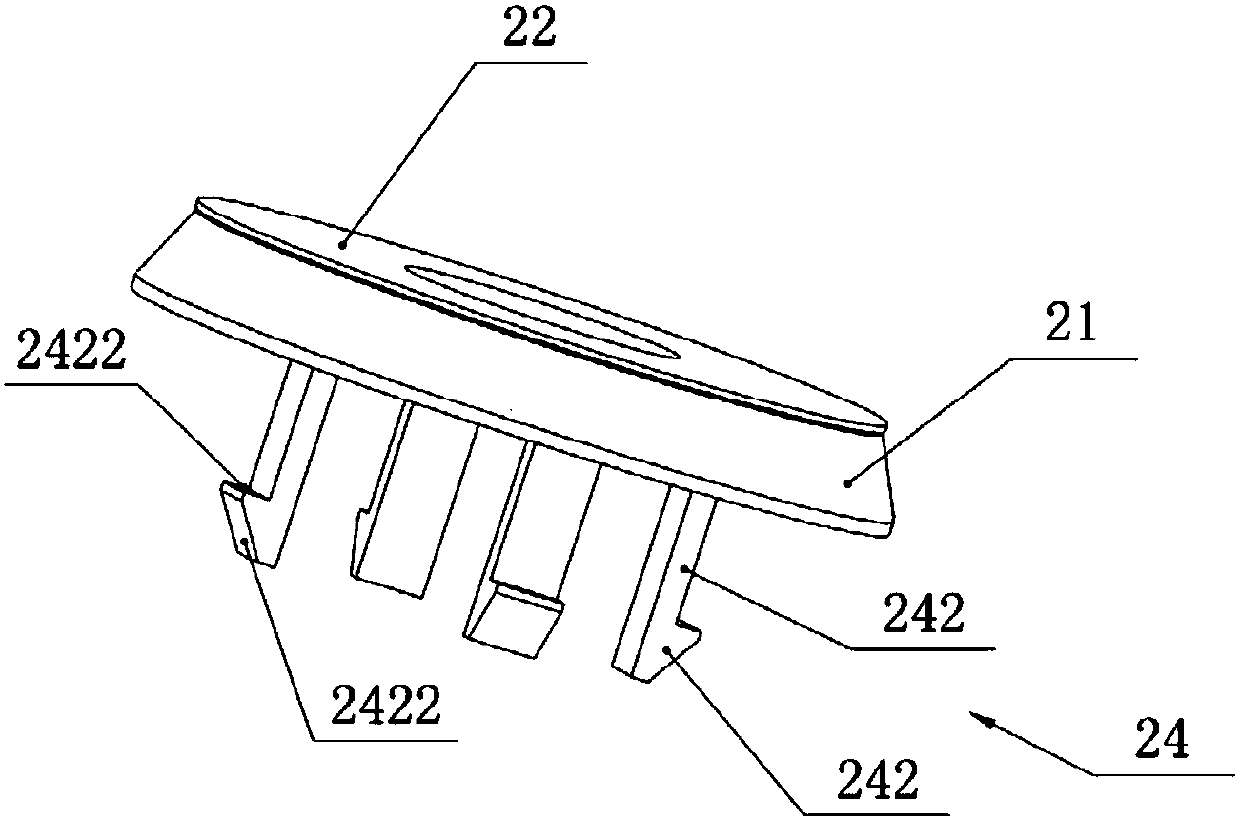
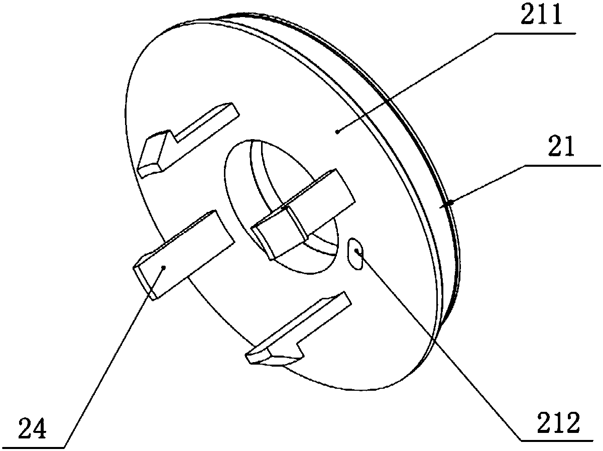
[0031] The light ring 2 is arranged above the potentiometer 1 and connected to the control board, and is co...


PUM


Abstract

The invention belongs to the gas cooker related field, and discloses a gas cooker light-emitting device and a gas cooker. The gas cooker light-emitting device comprises: a potentiometer located belowthe panel of the gas cooker, sleeving the valve rod of a gas valve and rotating with the valve rod; a lamp ring located above the potentiometer and locked on the outside of the panel, wherein the valve rod goes through the lamp ring; a knob fixedly connected to one end, going through the lamp ring, of the valve rod; a control plate connected to the potentiometer and the lamp ring respectively, wherein the control plate controls the on and off of the lamp ring and changes the luminescence color when the knob is pressed for igniting and the valve rod is rotated. When the knob is pressed for igniting and the valve rod is rotated, the flame size of the gas cooker changes with the rotation of the valve rod, the potentiometer also rotates with the valve rod, the resistance value of the potentiometer changes, a resistance value signal is sent to the control plate, and the control plate controls the lamp ring to emit lights having different colors according to different resistance values ofthe potentiometer to correspond to different flame sizes, so a user can easily determine the flame size according to the color of lights emitted by the lamp ring.

Description

technical field [0001] The invention relates to the related field of gas stoves, in particular to a gas stove lighting device and a gas stove. Background technique [0002] The flame indicator of the gas stove is usually made a groove on the knob or printed a logo as an indicator of the rotary position of the knob, which is not intuitive, and it is not easy to observe when the flame is adjusted, especially when the indoor light is dark, it is even more difficult to observe. [0003] In the prior art, some gas stoves are equipped with an LED light or a light ring directly under the knob, and the indicator mark is made of light-transmitting plastic material, so that the indicator mark can have a light effect. The light will pass through the knob, and the user can know whether the burner device is in the working state by checking whether the knob is luminous. If there is a flame, it means that it is in the working state, which increases human-computer interaction, and the light...

Claims


Application Information

Patent Timeline
IPC IPC(8): F24C15/12F24C3/12F21V33/00F21V23/04
CPCF21V23/04F21V33/0004F24C3/124F24C3/126F24C15/12
Inventor 王明琴陈雄刘衡
Owner QINGDAO HAIER WISDOM KITCHEN APPLIANCE CO LTD
Why Eureka
Try Eureka