
Drilling equipment for processing electric appliance switch element

A technology for electrical switches and drilling equipment, which is applied to metal processing equipment, electrical switches, electrical components, etc., and can solve problems such as difficult positioning, uneven holes, and hole position deviations, and achieves wide applicability and simple structure of the device , the effect of high drilling quality

Inactive Publication Date: 2018-05-11
ANHUI KAICHENG ELECTRIC APPLIANCE CO LTD
View PDF3 Cites 5 Cited by
  • Summary
  • Abstract
  • Description
  • Claims
  • Application Information

AI Technical Summary

Problems solved by technology

[0003] In the field of electrical switch element processing, drilling machines are often used to drill holes in the workpiece. The electrical switch elements to be processed are of different lengths and radians. It is difficult to fasten them with the fixture on the traditional drilling machine. As a result, during the drilling process, the workpiece is prone to shake and the hole is not smooth, which seriously affects the drilling quality. At the same time, it is difficult for the fixture on the traditional drilling machine to locate its arc surface, resulting in deviation of the hole position. For this reason, we A drilling equipment for electrical switch element processing is designed to solve the above problems

Method used


Image

  • Drilling equipment for processing electric appliance switch element
  • Drilling equipment for processing electric appliance switch element

Examples


Embodiment Construction

[0017] The following will clearly and completely describe the technical solutions in the embodiments of the present invention with reference to the accompanying drawings in the embodiments of the present invention. Obviously, the described embodiments are only some, not all, embodiments of the present invention.

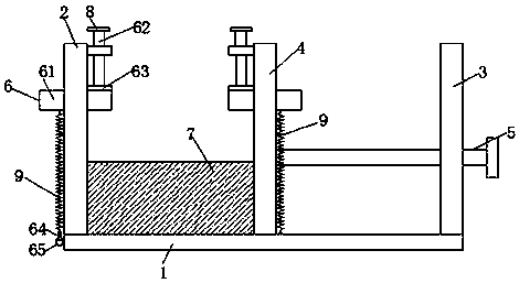
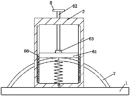
[0018] refer to Figure 1-2 , a kind of drilling equipment for the processing of electrical switch elements, comprising a base 1, a fixed plate 2 is vertically arranged on one side of the base 1, a limiting plate 3 is arranged on a side of the base 1 away from the fixing plate 2, and the limiting plate 3 and the fixed plate 2 are provided with an adjusting plate 4, and both ends of the adjusting plate 4 near the limiting plate 3 are provided with threaded rods 5, and the limiting plate 3 is provided with threaded holes matching the threaded rods 5, Between the fixed plate 2 and the adjusting plate 4, there is a switch element 7 for electrical appliances to be process...


PUM


Abstract

The invention discloses drilling equipment for processing an electric appliance switch element, and the equipment comprises a substrate. One side of the substrate is vertically provided with a fixed plate, and a side, far from the fixed plate, of the substrate is provided with a limiting plate. An adjustment plate is disposed between the limiting plate and the fixed plate, and two ends of a side,close to the limiting plate, of the adjustment plate are respectively provided with a threaded rod. The limiting plate is provided with threaded holes cooperating with the threaded rods, and a to-be-processed electric appliance switch element is clamped between the fixed plate and the adjustment plate. The fixed plate and the adjustment plate are respectively provided with a limiting device. Through the cooperation of the fixed plate and the adjustment plate, the equipment can limit the axial movement of the to-be-processed electric appliance switch element, and can limit the vertical movementof the to-be-processed electric appliance switch element through the cooperation of a threaded compression bar, a fixing compression plate and a fixing hook. The limiting of the threaded compressionbar and the fixing hook locates at two sides of the fixing compression plate, and is in opposite directions, thereby enabling the to-be-processed electric appliance switch element to be stable duringdrilling. The equipment is simple in structure, and is convenient to adjustment.

Description

technical field [0001] The invention relates to the field of drilling devices, in particular to a drilling device for processing electrical switch elements. Background technique [0002] The word switch is interpreted as on and off. It also refers to an electronic component that can open a circuit, interrupt the current flow, or cause it to flow to other circuits. The most common switches are human-operated electromechanical devices that have one or more electrical contacts. The "closed" of the contact means that the electronic contact is conductive and allows current to flow; the "open circuit" of the switch means that the electronic contact is not conductive to form an open circuit and does not allow current to flow. [0003] In the field of electrical switch element processing, drilling machines are often used to drill holes in the workpiece. The electrical switch elements to be processed are of different lengths and radians. It is difficult to fasten them with the fixt...

Claims


Application Information

Patent Timeline
IPC IPC(8): H01H11/00B23Q3/06
CPCH01H11/00B23Q3/062B23Q3/067
Inventor 刘开成
Owner ANHUI KAICHENG ELECTRIC APPLIANCE CO LTD
Learn More