Laser-machining head and laser-machining machine comprising same

A laser processing head, laser technology, applied in manufacturing tools, laser welding equipment, metal processing equipment and other directions, can solve problems such as adverse observation accuracy and influence

Active Publication Date: 2018-05-11
TRUMPF WERKZEUGMASCHINEN GMBH & CO KG
View PDF7 Cites 2 Cited by
  • Summary
  • Abstract
  • Description
  • Claims
  • Application Information

AI Technical Summary

Problems solved by technology

Furthermore, observation accuracy can also be adversely affected if the object plane is not oriented exactly perpendicular to the laser beam axis (and thus not exactly perpendicular to the observation axis)

Method used


Image

  • Laser-machining head and laser-machining machine comprising same
  • Laser-machining head and laser-machining machine comprising same
  • Laser-machining head and laser-machining machine comprising same

Examples


Embodiment Construction

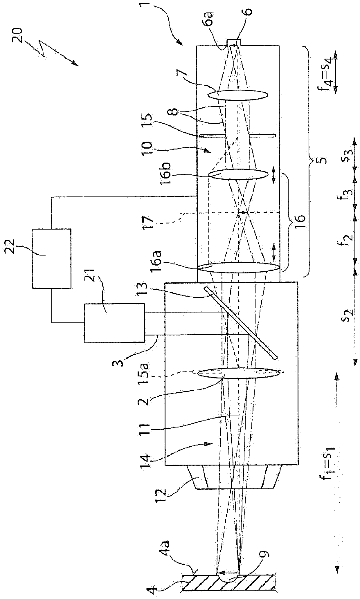
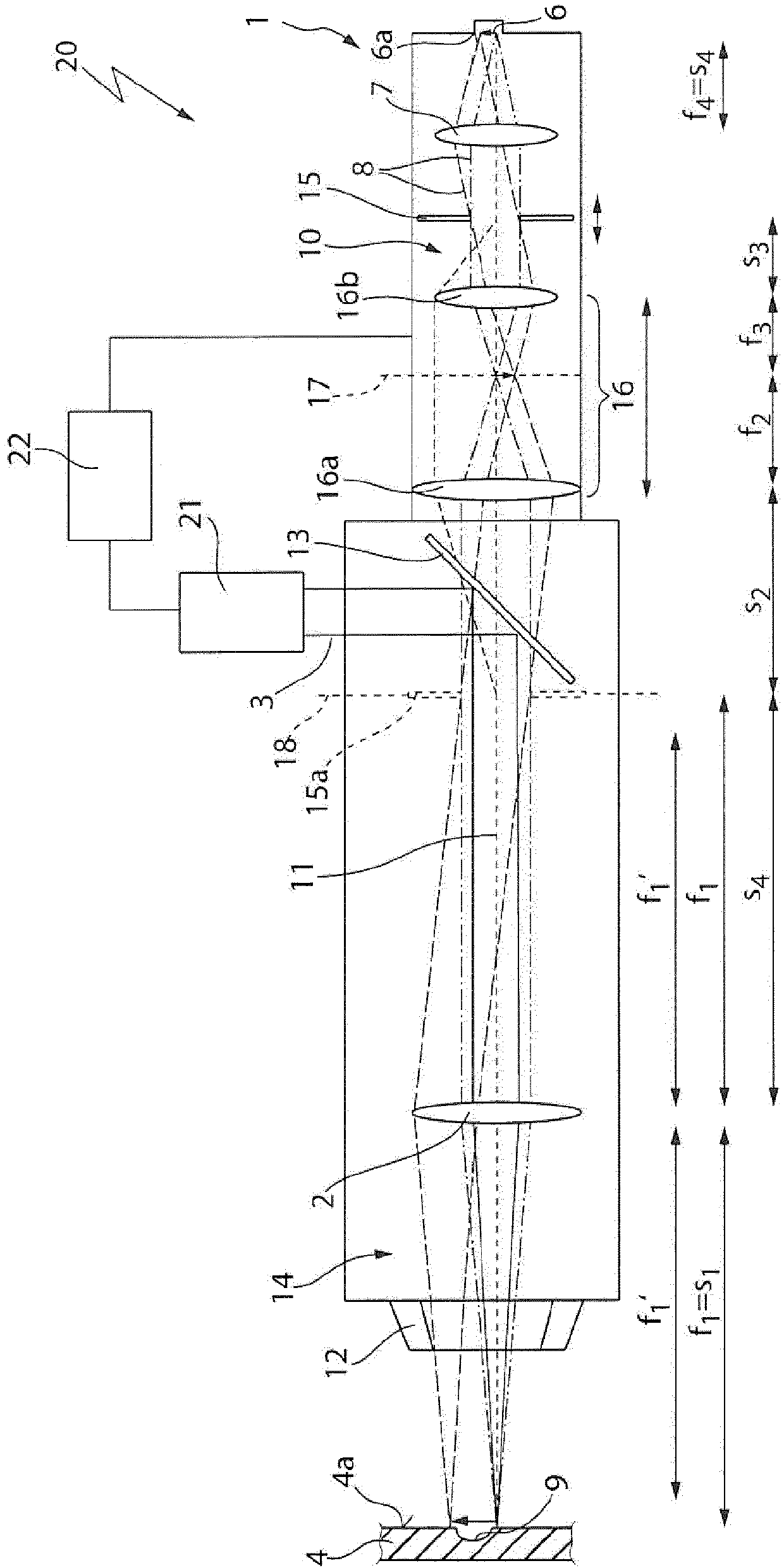
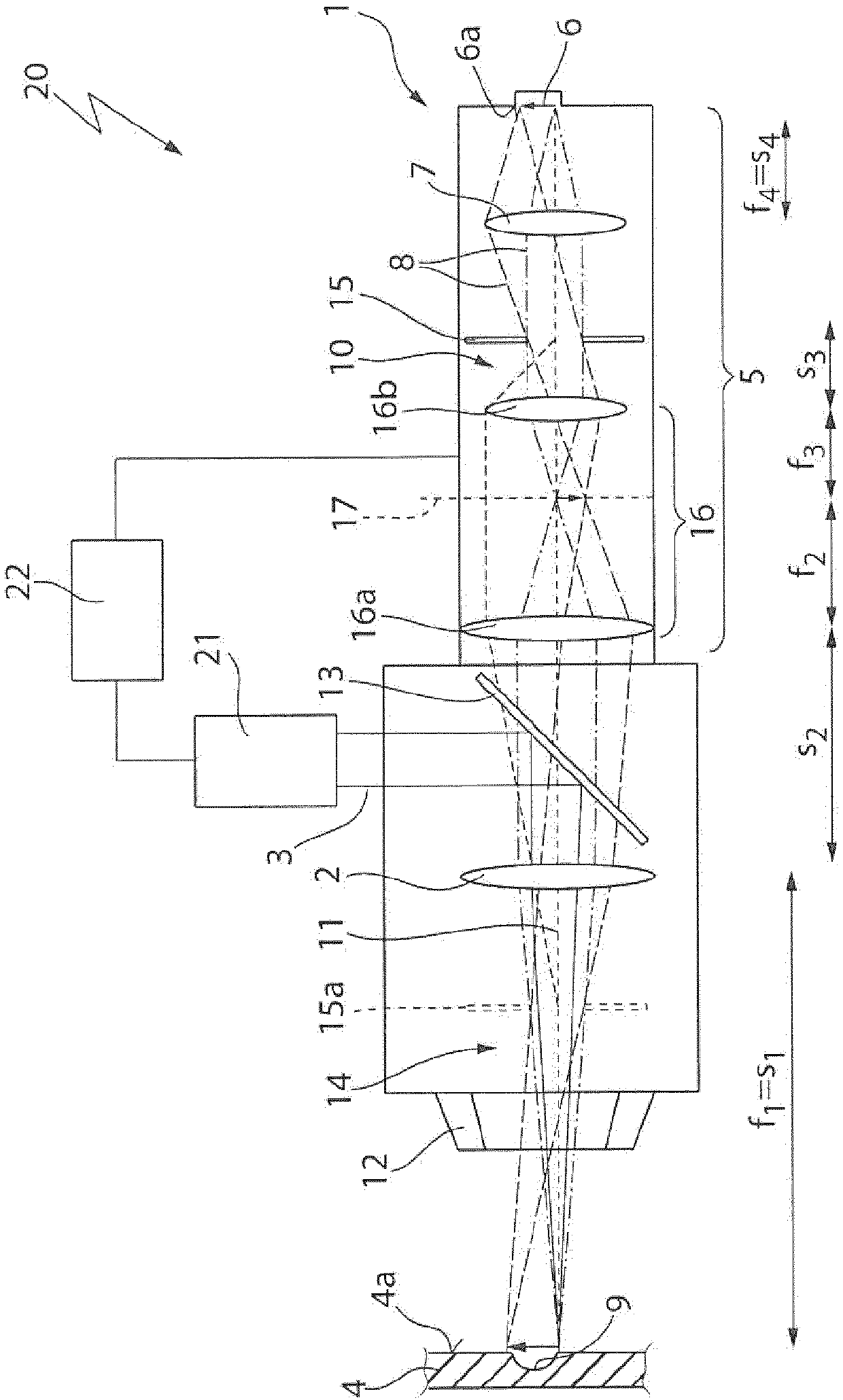
[0036] figure 1 The structure of a laser machining head 1 is shown by way of example, which has a focusing device in the form of a focusing lens 2 for focusing a machining laser beam 3 onto a workpiece 4 . In the example shown, the workpiece 4 , more precisely the workpiece surface 4 a is arranged at a distance with respect to the focusing lens 2 which corresponds to the focal length f of the focusing lens 2 . 1 or object distance s 1 . Furthermore, the laser processing head 1 has an optical imaging device 5 with a detector 6 . The optics 7 in the form of lenses are arranged with the detector 6 in the following distance - this distance is the focal length f of the optics 4 or object distance s 4 , and this optics together with the focusing lens 2 is used to image the workpiece surface 4a, which constitutes the object plane of the optical imaging device 5, onto the following image plane: The detector 6, more precisely the radiation-sensitive surface 6a of the detector 6, is...


PUM


Abstract

The invention relates to a laser-machining head (1) comprising the following: a focusing device (2) for focusing a machining laser beam (3) onto a workpiece (4) to be machined which is arranged in a machining beam path (14) of the machining laser beam (3); an optical imaging device (5) which comprises a detector (6) and which is designed to form a monitoring beam (8) from a machining region (9) ofthe workpiece (4) onto the detector (6) along a monitoring beam path (10) that passes through the focusing device (2); and a beam splitter (13) for separating the monitoring beam path (10) of the monitoring beam (8) from the machining beam path (14) of the machining laser beam (3). The laser-machining head (1) has an optical imaging device (5) optical imaging unit (16) arranged in the monitoringbeam path (10) between the beam splitter (13) and the detector (6) and a diaphragm (15) which is arranged between the optical imaging unit (16) and the detector (6) and which is spaced from the detector (6). The optical imaging unit (16) is designed to generate an image (15a) of the diaphragm (15) in the machining beam path (14) of the machining laser beam (3) between the beam splitter (13) and the workpiece (4). The invention also relates to a laser-machining machine (20) comprising such a laser-machining head (1) and a beam source (21) for generating the machining laser beam (3).

Description

technical field [0001] The invention relates to a laser processing head, comprising a focusing device, an optical imaging device and a beam splitter, wherein the focusing device is used to focus the processing laser beam on the workpiece to be processed, the focusing device arranged in the processing beam path of the processing laser beam, the optical imaging device includes a detector and is configured to image observation radiation onto the detector from the processing region of the workpiece along the observation beam path through the focusing device, The beam splitter serves to separate the viewing beam path of the viewing radiation from the processing beam path of the processing laser beam. The invention also relates to a laser processing machine having such a laser processing head. Background technique [0002] In the case of laser material processing, the processing laser beam is guided along the processing beam path by an optical device consisting of lenses and / or m...

Claims


Application Information

Patent Timeline
Patent Type & Authority Applications(China)
IPC IPC(8): B23K26/03B23K26/06B23K26/38B23K31/12
CPCB23K26/0626B23K26/38B23K31/125B23K26/032B23K26/046B23K26/0648B23K26/0676
Inventor B·雷加阿尔德
Owner TRUMPF WERKZEUGMASCHINEN GMBH & CO KG
Why Eureka
Try Eureka