Method for guiding a machining head along a track to be machined

A technology for processing and processing heads, which is applied in metal processing equipment, manufacturing tools, welding equipment, etc., and can solve problems such as errors

Inactive Publication Date: 2018-05-11
PRECITEC GMBH
View PDF9 Cites 1 Cited by
  • Summary
  • Abstract
  • Description
  • Claims
  • Application Information

AI Technical Summary

Problems solved by technology

[0004] In addition, errors may occur due to changes in the distance from the workpiece surface to the focal point position

Method used


Image

  • Method for guiding a machining head along a track to be machined
  • Method for guiding a machining head along a track to be machined

Examples


Embodiment Construction

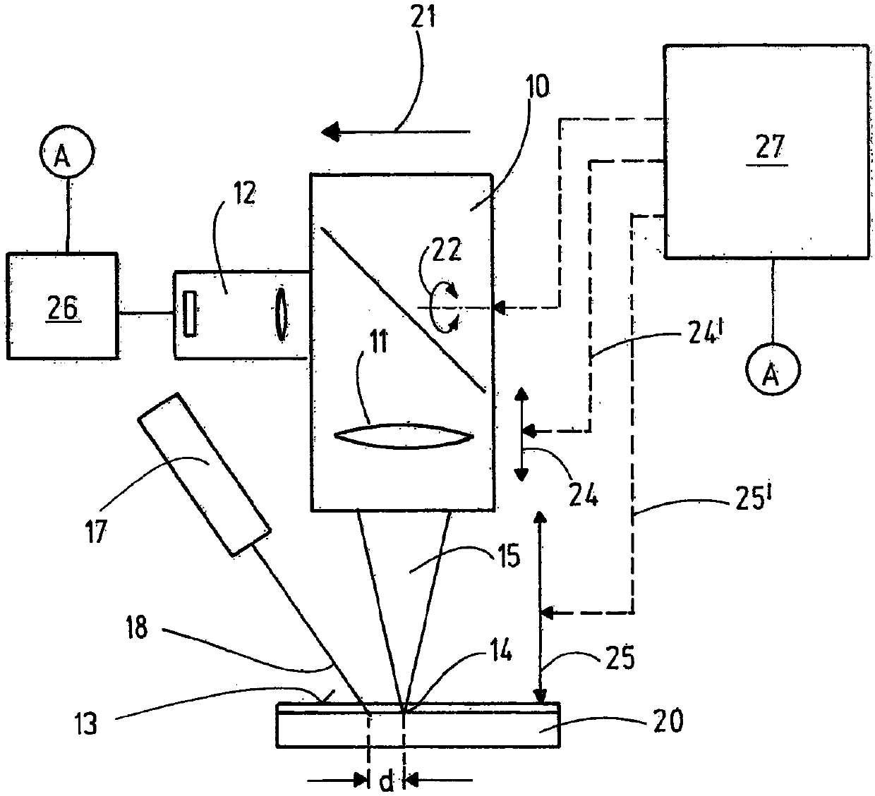
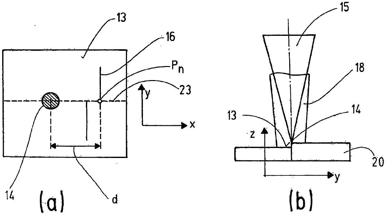
[0021] figure 1 A machining head, in particular a laser machining head 10, is shown in a very simplified manner with a beam-shaping optics 11 and a camera 12 and light 16 for viewing the workpiece surface 13 in the region of the point of incidence 14 of the machining laser beam 15 , which is also referred to below simply as laser beam 15 , which is projected by a light-section projector 17 by means of a light fan 18 onto the surface 19 of the workpiece 20 .

[0022] The laser processing head 10 is guided in the feed direction 21 by a machine control device (not shown in detail) at a speed corresponding to the processing process. As indicated by the double arrow 22, the laser processing head 10 can be pivoted or also moved laterally in order to keep the point of incidence 14 of the laser beam 15 precisely on the trajectory 23 to be processed, ie between the two workpiece parts on the butt seam. The machine controls are also used to adjust the beam shaping optics 11 , in parti...


PUM


Abstract

The invention relates to a method for guiding a machining head, in particular a laser machining head (10), along a track (23) to be machined, in which a line of light (16) is projected onto the track(23) to be machined, transversely with respect to the latter, at a distance (d) in front of the machining point (14) in the machining direction, in which, from images of the line of light (16) recorded continuously during the machining, the position y(Pn) of the track (23) in front of the machining point (14) is determined, and in which the machining point (14) is aligned with the track (23) as soon as the machining point (14) reaches the respective point (Pn) on the track (23) for which the position y(Pn) of the track (23) was determined. In order to guide the machining point (14), that is tosay in particular the focus of a machining laser beam, precisely along the track (23) to be machined, that is to say along a seam or joint to be joined, provision is made for the current machining speed at which the machining point (14) is guided along the track (23) to be machined to be measured, and that, from the distance (d) of the line of light (16) from the machining point (14) and the current machining speed, the time at which the machining point reaches the respective point (Pn) of the track (23) is determined.

Description

technical field [0001] The invention relates to a method for guiding a machining head, in particular a laser machining head, along a path to be machined, in particular along a butt joint or abutment seam between two joining partners to be welded to each other. Background technique [0002] When welding with laser radiation, the laser beam must be precisely aimed at the butt joints or butt seams of the joint objects to be welded, with its focal point forming the machining point. For this purpose, seam tracking systems are used, which by means of triangulation sensors detect the actual position of the seam or butt seam, ie the trajectory to be machined. In these systems, the distance from the light projected before the point of incidence of the laser beam on the workpiece to the point of incidence of the laser beam and the feed rate of the point of incidence of the laser, ie the machining point, are specified as parameters. [0003] The disadvantage of this approach is that i...

Claims


Application Information

Patent Timeline
Patent Type & Authority Applications(China)
IPC IPC(8): B23K26/044B23K26/04B23K26/28B23K26/26
CPCB23K26/048B23K26/26B23K26/28B23K26/044
Inventor F·阿格拉瓦尔S·比尔曼斯J·施瓦茨E·苏佩尔诺克
Owner PRECITEC GMBH
Why Eureka
Try Eureka