Strip puncher pin connecting structure for powder forming equipment
A technology of forming equipment and connecting structure, which is applied in the field of connecting structure of long punches for powder forming equipment, can solve the problems of waste, reduce the service life of punches, cannot guarantee the verticality and parallelism of punches, etc., so as to reduce production Cost, prolong service life, increase the effect of aesthetic appearance
- Summary
- Abstract
- Description
- Claims
- Application Information
AI Technical Summary
Problems solved by technology
Method used
Image

Examples
Embodiment Construction
[0018] In order to make the technical problems, technical solutions and beneficial effects solved by the present invention clearer, the present invention will be further described in detail below in conjunction with the accompanying drawings and embodiments. It should be understood that the specific embodiments described here are only used to explain the present invention, not to limit the present invention.
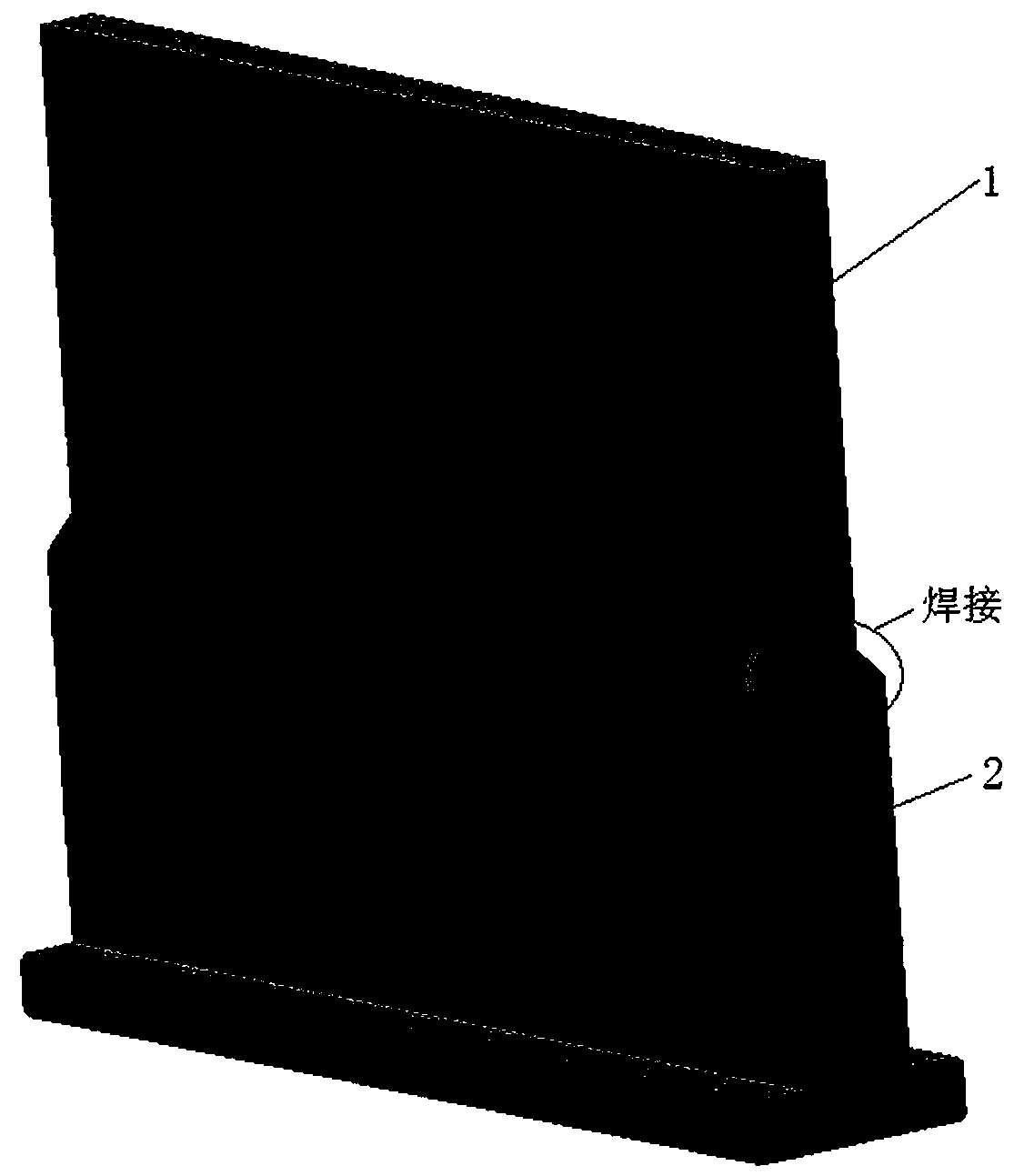
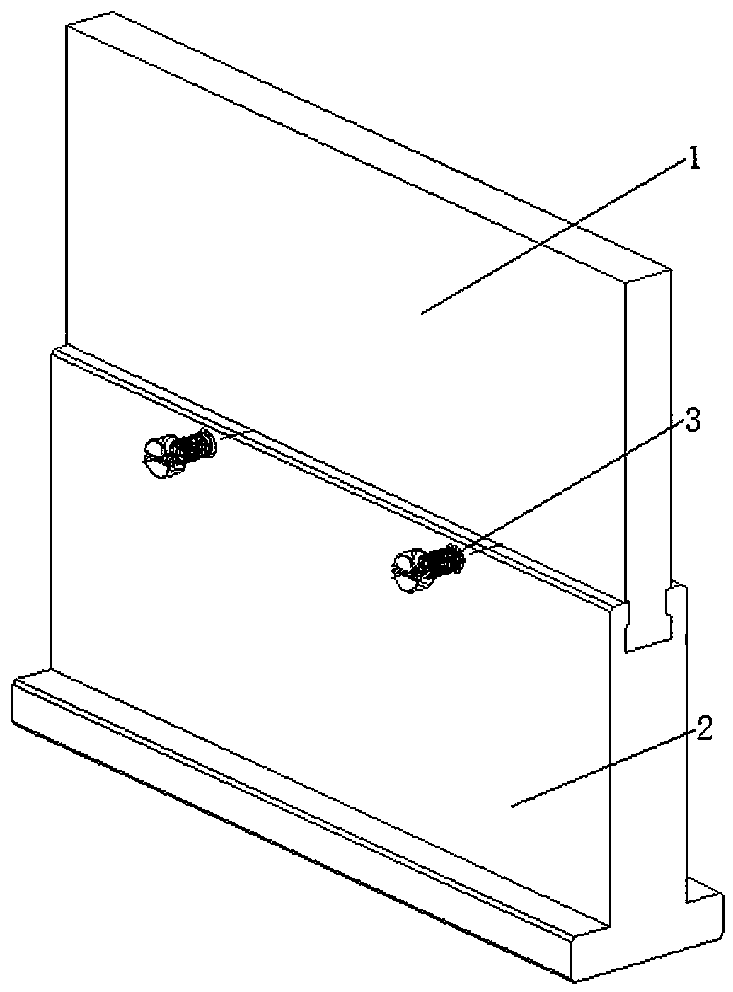
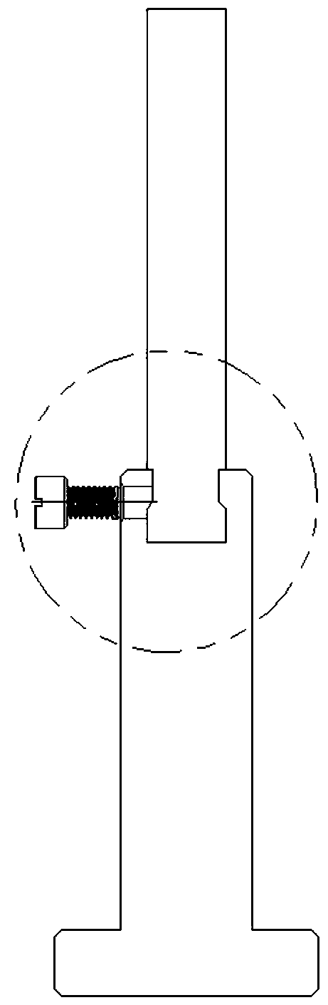
[0019] Please also refer to Figure 1 to Figure 6 According to an embodiment of the present invention, a long punch connection structure for powder molding equipment is provided, which is composed of a punch seat, a long punch and a screw. The end of the punch seat in contact with the long punch is designed with a dovetail groove, and the end of the long punch in contact with the punch seat is designed to match the shape of the dovetail groove, and the gap between the punch seat and the long punch fit, fixed by screw. The assembly of the punch seat and the shown long p...
PUM
 Abstract
Description
Claims
Application Information
 - R&D
- Intellectual Property
- Life Sciences
- Materials
- Tech Scout
- Unparalleled Data Quality
- Higher Quality Content
- 60% Fewer Hallucinations
Browse by: Latest US Patents, China's latest patents, Technical Efficacy Thesaurus, Application Domain, Technology Topic, Popular Technical Reports.
© 2025 PatSnap. All rights reserved.Legal|Privacy policy|Modern Slavery Act Transparency Statement|Sitemap|About US| Contact US: help@patsnap.com