Rigid and flexible two-stage locking ball joint

A ball joint and locking ball technology, applied in the field of medical devices, can solve the problems of not being able to operate multiple surgical tools and instruments at the same time, and the operator of clamping surgical tools and instruments cannot operate at the same time, so as to improve the experimental efficiency and Success rate, avoiding overwork, reducing labor intensity

Active Publication Date: 2018-05-15
HARBIN INST OF TECH SHENZHEN GRADUATE SCHOOL
View PDF9 Cites 5 Cited by
  • Summary
  • Abstract
  • Description
  • Claims
  • Application Information

AI Technical Summary

Problems solved by technology

[0004] The present invention provides a rigid-flexible two-stage locking ball joint, in order to solve the problem that in medical treatment and medical experiments, the operators who need to clamp surgical tools and instruments cannot operate at the same time, and many instruments need the assistance of additional assistants. Tight joints can form a manipulator arm in a multi-joint configuration, which can position surgical tools and instruments
Solve the problem of operators not being able to operate multiple surgical tools and instruments at the same time

Method used


Image

  • Rigid and flexible two-stage locking ball joint
  • Rigid and flexible two-stage locking ball joint
  • Rigid and flexible two-stage locking ball joint

Examples


Embodiment 1

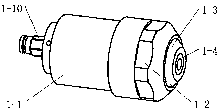
[0028] refer to figure 1 , a rigid-flexible two-stage locking ball joint according to the present invention, its external basic structure is composed of a joint sleeve 1-1, a ball joint cover 1-2, a spherical part 1-3 and a fluid quick connector 1-10. Among them, the ball joint cover 1-2 is connected with the joint sleeve 1-1 through threads, and the outer circumference of the ball joint cover 1-2 has a tightening structure to tighten the two; the fluid quick connector 1-10 is installed on the joint sleeve 1-1 Tail, for the fluid inlet;

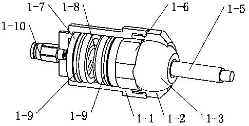
[0029] refer to figure 2 , The ball joint module is composed of a ball joint metal bush 1-4 embedded in the spherical part 1-3, and a connecting rod 1-5 constitutes the ball joint movement part. The main piston 1-6 and the secondary piston 1-7 are covered with a sealing ring 1-9, which can slide in the inner cavity of the joint sleeve 1-1; the main piston 1-6 and the secondary piston 1-7 are installed There is a spring 1-8, and the spring 1...

Embodiment 2

[0035] This embodiment is transformed on the basis of Embodiment 1. In this embodiment, the ball joint module 1 in Embodiment 1 is replaced by a ball joint 4 with a concentric ventilation structure. The concentric ventilation structure can maintain the locking function while The fluid of the ball joint is allowed to flow into the lumen of the adjacent ball joint through the internal flow passage of the local joint. When the concentric ventilation structure ball joint 4 is expanded, one fluid inlet can be used to see that the inner cavities of other ball joints are completely filled.

[0036] see Figure 6 , the concentric air ball joint 4 is composed of a joint sleeve 1-1, a ball joint cover 1-2 and a masonry spherical part 4-3, a ball joint metal bushing 4-4, a hose 4-5, a main piston 4-6, The secondary piston 4-7, the sliding joint 4-8, the sealing ring 4-9, the inner ring sealing ring 1-10 and the fluid quick connector 1-10 are composed. Among them, the ball joint cover 1...

Embodiment 3

[0041] The present embodiment is transformed on the basis of the second embodiment. The exhaust valve 6-3 in the second embodiment can also close the flexible pipe 4-5 at one end of the concentric ventilation ball joint 4 at the end, and other parts are not Change, also realize the locking function.


PUM


Abstract

The invention discloses a rigid and flexible two-stage locking ball joint. A two-stage piston is arranged in the ball joint; a two-stage locking state is realized; when the fluid pressure is not sufficient to simultaneously push the two-stage piston, the ball joint is in a flexible locking state; when the fluid pressure can simultaneously push the two-stage piston, the ball joint is in a rigid locking state. Through a connecting sleeve, the ball joint is fixed with the head end and the tail end of the sleeve to form a ball joint connecting rod; then, the two or a plurality of ball joint connecting rods are connected; a multi-freedom operation arm can be formed; a tool or an operation appliance can be positioned; when different pressure is exerted on each connecting rod, the locking state of the ball joint can be controlled so as to adapt to different joint loads.

Description

technical field [0001] The invention belongs to the field of medical instruments, and in particular relates to a joint locking device. Background technique [0002] In medical operations and medical experiments, due to the need to use a variety of instruments in operations and experiments, the operator cannot operate many instruments at the same time, and additional assistants are needed to perform operations and experiments. Increased manpower expenditure, if the operation and experiment time is too long, the operator and assistant are prone to fatigue, and the hand-held instrument is unstable. Therefore, there is a need for a device that can help the operator to stably position the surgical instrument and the experimental tool, and adapt to different operation tasks. [0003] Patent CN201710683947.0 discloses a scheme of medical aids, in which the helical pair squeezes the ball joint to lock. First of all, this method cannot simultaneously lock and unlock all kinematic j...

Claims


Application Information

Patent Timeline
Patent Type & Authority Applications(China)
IPC IPC(8): F16C11/06F16C11/10A61B34/00
CPCF16C11/06F16C11/10A61B34/70
Inventor 李鹏宋国立
Owner HARBIN INST OF TECH SHENZHEN GRADUATE SCHOOL
Why Eureka
Try Eureka