
Efficient electric furnace system

An electric furnace, high-efficiency technology, applied in the direction of electric furnace heating, furnace, crucible furnace, etc., can solve the problems of low working efficiency and narrow application range of the electric furnace system, and achieve the effect of facilitating later use, high working efficiency and simple control process

Pending Publication Date: 2018-05-15
江苏迈路达节能新材料科技有限公司
View PDF9 Cites 0 Cited by
  • Summary
  • Abstract
  • Description
  • Claims
  • Application Information

AI Technical Summary

Problems solved by technology

[0002] The electric furnace occupies an increasingly important position in the fields of steelmaking and melting. The electric furnace system does not only refer to the electric furnace itself. The electric furnace cooperates with other external devices to form a whole electric furnace system. In the prior art, the electric furnace system is usually equipped with The material part, the main body of the electric furnace and the discharge part, the addition of other appendages and the control of the addition of appendages in the production process cannot meet people's requirements, making the electric furnace system low in efficiency and narrow in scope of application

Method used


Image

  • Efficient electric furnace system
  • Efficient electric furnace system
  • Efficient electric furnace system

Examples


Embodiment Construction

[0025] The specific embodiments of the present invention will be further described in detail below in conjunction with the accompanying drawings.

[0026] The high-efficiency electric furnace system of this embodiment includes

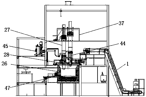
[0027] Feeding device 1, which feeds raw materials into the electric furnace;

[0028] Additive adding device, add additives to the inside of the electric furnace, and mix with raw materials to form products;

[0029] The additive adding device comprises a raw material tank, a mixing tank and a flow chute, the raw material tank comprises a first resin storage tank 2, a second resin storage tank 3 and an ammonia water tank 4, the output ends of the first resin storage tank and the second resin storage tank After the resin metering pump 5 flows into the mixing tank 6, the output end of the ammonia water tank 4 and the external water source flow into the mixing tank 6 through the pipelines 7 and 8 respectively, and after the stirring and mixing are coole...


PUM


Abstract

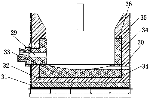
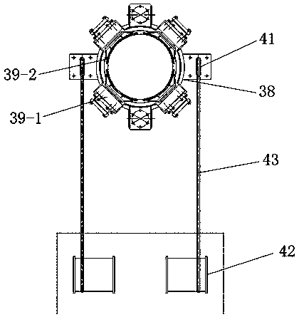
The invention provides an efficient electric furnace system, belongs to the field of electric melting furnace devices, and aims to solve the problems that in a production process, control over addition of other attachments and addition of attachments cannot meet demands of people, and thus, an electric furnace system is low in working efficiency and narrow in application range. The efficient electric furnace system comprises a feeding device, an additive adding device and an electric furnace device, a discharged material conveying device and an attached product conveying device, wherein the electric furnace device comprises an electric furnace and an electrode; a cloth device is mounted at the upper end of the electric furnace; the lower end of the electrode partially extends into the electric furnace; a stream flowing opening is formed in a side wall of the electric furnace; the discharged material conveying device is provided with a conveying device at an outlet of the electric furnace, and directly conveys discharged materials to a next station for follow-up treatment; the attached product conveying device comprises a track and a trolley; the trolley is mounted on the track; thetrack extends to a molten iron collecting position from the position of the stream flowing opening; and the trolley moves on the track in a reciprocating manner. The efficient electric furnace systemis complete in function, the working efficiency of the electric furnace system is high, a control process is simple and convenient, the use amount is accurate, later-period utilization of products isfacilitated, and meanwhile, waste of raw materials is also avoided.

Description

technical field [0001] An electric furnace system belongs to the field of electric furnace devices, and mainly relates to a high-efficiency electric furnace system. Background technique [0002] The electric furnace occupies an increasingly important position in the fields of steelmaking and melting. The electric furnace system does not only refer to the electric furnace itself. The electric furnace cooperates with other external devices to form a whole electric furnace system. In the prior art, the electric furnace system is usually equipped with The material part, the main body of the electric furnace and the discharge part, the addition of other appendages and the control of the addition of appendages in the production process cannot meet people's requirements, making the electric furnace system low in efficiency and narrow in scope of application. Contents of the invention [0003] In order to solve the above-mentioned problems, the present invention discloses a high-e...

Claims


Application Information

Patent Timeline
IPC IPC(8): F27B14/06F27B14/16F27B14/08F27B14/14F27B14/18F27D11/10
CPCF27B14/06F27B14/08F27B14/0806F27B14/14F27D11/10
Inventor 不公告发明人
Owner 江苏迈路达节能新材料科技有限公司
Learn More