Stacking ring shearing box and stacking ring shearing test based on stacking ring shearing box

A technology of shear box and wall ring, which is applied in the direction of applying stable shear force to test the strength of materials, measuring devices, instruments, etc., and can solve the problem of small shear distance in direct shear test, affecting experimental results, and fault tolerance of fixed shear surface Low rate and other issues

Pending Publication Date: 2018-05-15
FUJIAN GEOLOGICAL ENG SURVEY INST
View PDF10 Cites 5 Cited by
  • Summary
  • Abstract
  • Description
  • Claims
  • Application Information

AI Technical Summary

Problems solved by technology

However, the test box of the direct shear instrument is a rigid body and uses a fixed shear surface. The main problems brought about by this method are: 1. Before the shear failure, the sample lacks elastic deformation and plastic deformation stages, and only shows sliding after failure. Displacement, the failure area is a plane, while the general soil shear failure area is distributed in a band shape, the soil has a certain elastic-plastic deformation, and its deformation is continuous before failure; 2. Because the shear box limits the size of the sample Deformation, resulting in uneven stress distribution in the shear box, resulting in different compressive stress from the preset situation; 3. The use of a fixed shear surface has a low error tolerance rate and is sensitive to the uniformity of the sample, and its results are easily affected by the hardness near the shear surface. Influenced by inhomogeneous substances such as blocks and defects; 4. During the shearing process, due to the staggering of the upper and lower samples, the shear area changes, which affects the experimental results; 5. The direct shear test has a small shear distance and cannot complete large displacement cut
Although the triaxial test provides a certain degree of freedom for the width and position of the shear plane, it also has the problem of being easily affected by inhomogeneous substances such as hard blocks and defects near the shear plane, and the shear distance is small
However, since it still uses a single shear plane, the result is still sliding displacement without considering other deformation conditions, and it is still sensitive to the uniformity of the sample
In addition, due to the limited height of the shear box, it is also impossible to complete the stress-strain state research of complex structural soil layers or contact surfaces of different materials.

Method used


Image

  • Stacking ring shearing box and stacking ring shearing test based on stacking ring shearing box
  • Stacking ring shearing box and stacking ring shearing test based on stacking ring shearing box
  • Stacking ring shearing box and stacking ring shearing test based on stacking ring shearing box

Examples


example 1

[0074] Example 1: Traditional Ring Shear Test

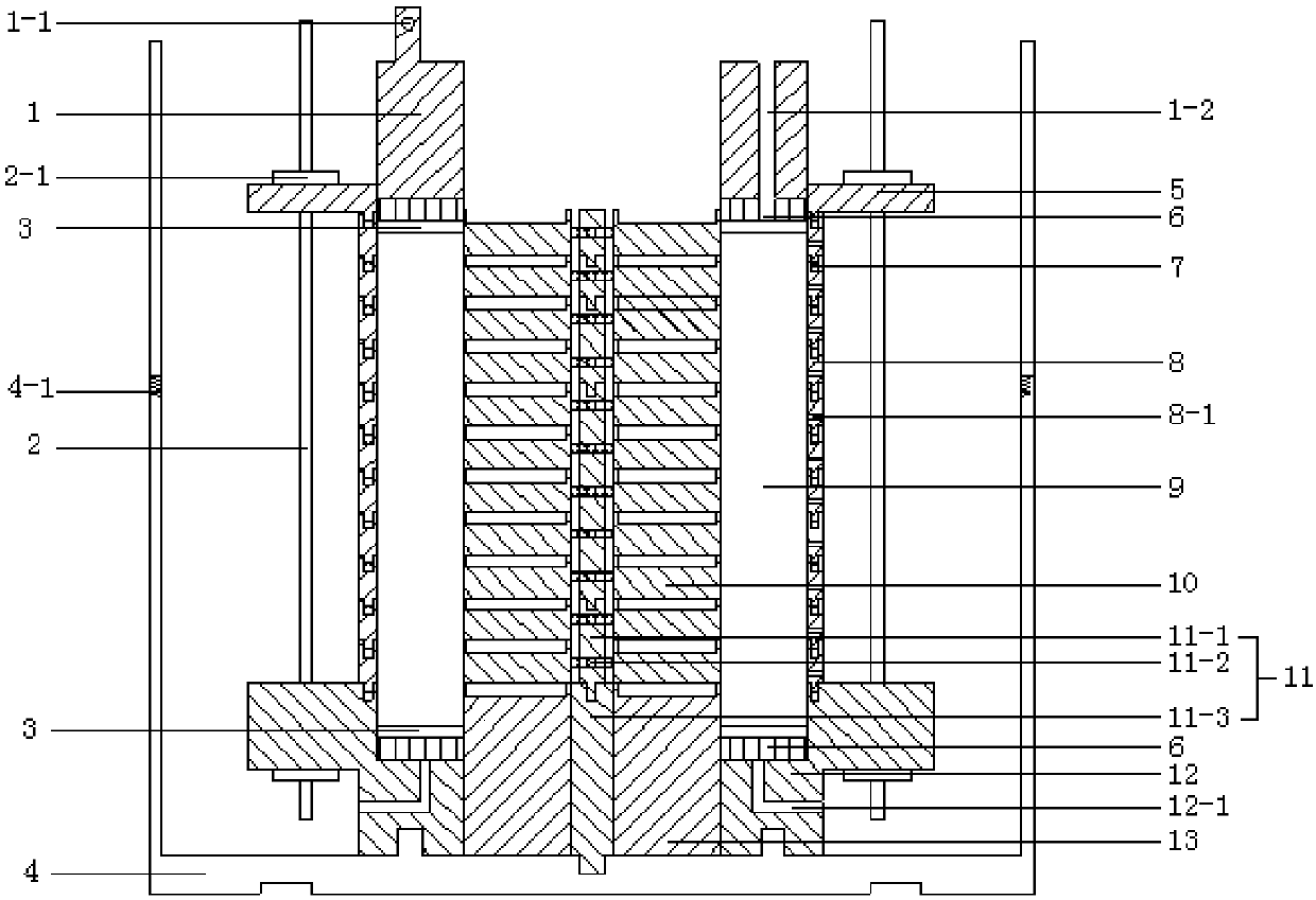
[0075] To carry out the traditional ring shear test, it is only necessary to remove the redundant shear box unit and only keep one shear box unit. During the test, the vertical stress is transmitted and consolidated through the cutter head 1, and the torque is transmitted through the lower shear box 12 during the test, so that The sample is sheared circumferentially along the preset shear plane.

example 2

[0076] Example 2: Stacked Ring Shear Test of Remodeled Soil

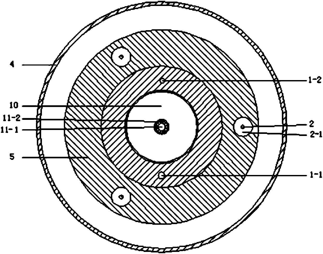
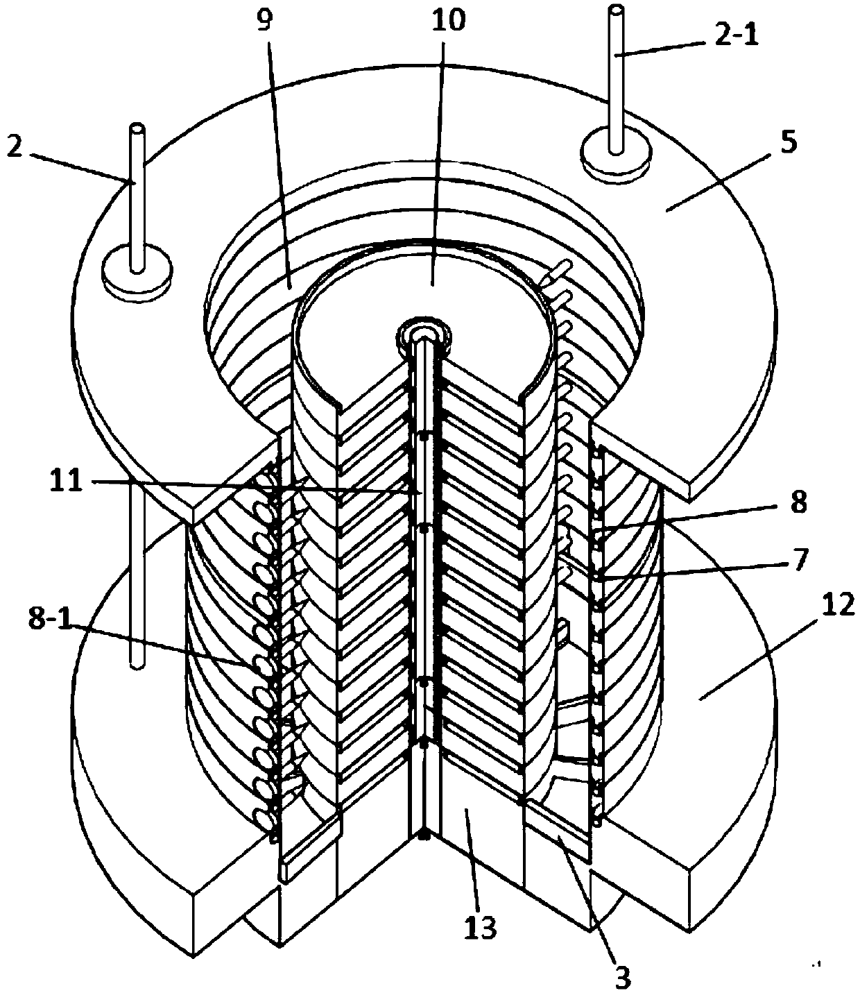
[0077] The remolding soil sample preparation process adopts the layered sample preparation mode. First, place the bottom column 13 in the round hole of the lower shear box 12, and insert the fixed shaft 11-3 to fix it. Place the second ball in the annular groove of the lower shear box 12, add a certain amount of lubricating oil, and put a movable wall ring 8 to form the bottom sample groove. Put the soil sample into the sample groove, compact it layer by layer to the height of the wall ring, then place balls in the groove of the upper wall ring and put a layer of wall ring and stack ring. Repeat the above until the required height for the test is reached. Put on the collar 5, insert the shear box support 2 and lock it with the nut 2-1 to complete the sample preparation. After the sample preparation is completed, the completed assembly is moved to the water bath box 4, and the vertical pressure is applied to the sa...

example 3

[0078] Example 3: Undisturbed soil stacked ring shear test

[0079] The sample preparation of the undisturbed soil-stacked ring shear test needs the help of a sample preparation device, which is a cylindrical thin-walled ring cutter, which is characterized in that the assembled movable ring group can be embedded in the cylinder in advance. Insert the sampler together with the movable ring group into the undisturbed soil to take soil samples. Take off the sample preparation device, place the movable ring group and the sample on the lower shear box 12, and ensure that the protrusion on the movable ring 8 engages with the groove of the lower shear box 12. The undisturbed soil is pressed into the lower shear box 12 grooves, and the redundant movable wall ring 8 is sloughed off. Then, a hole is opened in the center of the sample through a ring knife with the same diameter as the lamination. The ring knife is inserted from the upper part of the sample and penetrates to the round ho...


PUM


Abstract

The invention belongs to the technical field of rock ring shear tests, and relates to a stacking ring shearing box and a stacking ring shearing test based on the stacking ring shearing box. The stacking ring shearing box comprises a water bath mechanism, a test sample chamber mechanism and a test sample fixing mechanism, wherein the water bath mechanism comprises a water baht box; the test specimen chamber mechanism is arranged in the water bath box; a groove is formed in the center position of the bottom surface of the water bath box; two or more than two bulges are arranged on one circumference using the center position as the circle center; the water bath box can rotate through being driven by an external twisting mechanism; the unlimited deformation stacking ring type annular shearingof the different-height rock soil test can be met; in addition, in the annular shearing process, certain freedom and continuity of a test sample are ensured; the stacking ring shearing box and the stacking ring type shearing test can be used for studying the contact surface deformation rules of different materials, simulating complicated structure soil layer slide long-distance deformation and searching soft and weak layers.

Description

technical field [0001] The invention belongs to the technical field of rock-soil ring shear testing, and relates to a ring-folding shear box and a ring-folding shear test based on the ring-folding shear box. Background technique [0002] The mechanical characteristics of soil and the deformation state when subjected to external force are the basic subjects in the field of rock and soil mechanics, and are also one of the most concerned conditions in geotechnical engineering construction. For this reason, people have developed a variety of instruments and equipment such as direct shear test, triaxial test, simple shear test, and ring shear test to explore the above content, and have a mechanical model based on material mechanics for analysis. The ultimate goal is to simulate as much as possible The stress-strain characteristics of the soil in actual conditions, so as to obtain its strength parameters. [0003] But it is worth noting that the soil is composed of countless comp...

Claims


Application Information

Patent Timeline
Patent Type & Authority Applications(China)
IPC IPC(8): G01N3/24G01N3/02
CPCG01N3/02G01N3/24
Inventor 陈志超柳侃叶龙珍罗旋
Owner FUJIAN GEOLOGICAL ENG SURVEY INST
Why Eureka
Try Eureka