Conveniently-pluggable FC-type fiber optic joint and operation method thereof
A fiber optic connector, a convenient technology, applied in the field of FC fiber optic connectors that are easy to plug and unplug, can solve the problems of time-consuming installation, low work efficiency, and discomfort of the operator's hands, so as to improve installation efficiency, simple structure, and save operation time Effect
- Summary
- Abstract
- Description
- Claims
- Application Information
AI Technical Summary
Problems solved by technology
Method used
Image

Examples
Embodiment Construction
[0038] The present invention will be further described below in conjunction with the accompanying drawings and specific embodiments. The schematic embodiments and descriptions of the present invention are used to explain the present invention, but are not intended to limit the present invention.
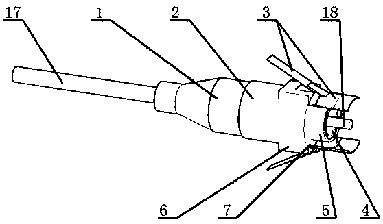
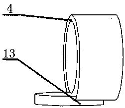
[0039] Such as figure 1 , 2 , 3, 4, and 5 show a conveniently pluggable FC-type optical fiber connector, used with FC-type optical distribution flange 16, including rubber sheath 1, fixed protective sleeve 2, connection assembly 3, inner frame sleeve 4, elastic Ferrule 5, joint section 18. The rubber sheath 1 is connected with the fixed protective cover 2, the fixed protective cover 2 is a cylinder with a rectangular boss 6, the rectangular boss 6 is located on the upper and lower outer surfaces of the right end of the fixed protective cover 2, and the right side of the rectangular boss 6 has a plug Slot 7.
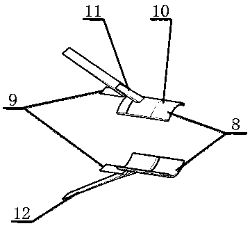
[0040] The connection assembly 3 includes a U-shaped locking clip 8 and ...
PUM
 Abstract
Description
Claims
Application Information
 - R&D
- Intellectual Property
- Life Sciences
- Materials
- Tech Scout
- Unparalleled Data Quality
- Higher Quality Content
- 60% Fewer Hallucinations
Browse by: Latest US Patents, China's latest patents, Technical Efficacy Thesaurus, Application Domain, Technology Topic, Popular Technical Reports.
© 2025 PatSnap. All rights reserved.Legal|Privacy policy|Modern Slavery Act Transparency Statement|Sitemap|About US| Contact US: help@patsnap.com