Vibe and disparity map background subtraction method-based moving target detection method

A moving target, background difference method, applied in the field of computer vision, can solve the problems of poor environmental adaptability, easy to be affected by external conditions, dynamic changes, etc., to avoid lighting and shadows, and eliminate ghosting effects.

Inactive Publication Date: 2018-05-15
HUNAN VISION SPLEND PHOTOELECTRIC TECH
View PDF7 Cites 13 Cited by
  • Summary
  • Abstract
  • Description
  • Claims
  • Application Information

AI Technical Summary

Problems solved by technology

The optical flow method requires special hardware support, and the calculation is complex and computationally intensive, so it is generally less used
The principle of the inter-frame difference method is simple and insensitive to noise and light changes, but the target detection results are prone to holes
The background difference method can extract the complete information of the target, but it is easily affected by the dynamic changes of the external scene such as lighting
When the moving object changes slowly to fast motion, the background difference method can easily detect the background exposed area (that is, the current background still has the moving object information of the previous frame, but the moving object is no longer in this area) as the foreground. The phenomenon of "shadow" appears, and the noise processing effect is not good in complex scenes such as tree branches swinging, and the adaptability to the environment is poor. Such false detections will cause difficulties in subsequent target tracking.
The traditional moving target detection method based on monocular vision can detect the outline of the moving target, but it is easily affected by external conditions, and will detect shadows and part of the background as foreground

Method used


Image

  • Vibe and disparity map background subtraction method-based moving target detection method
  • Vibe and disparity map background subtraction method-based moving target detection method
  • Vibe and disparity map background subtraction method-based moving target detection method

Examples


Embodiment Construction

[0045] The following will clearly and completely describe the technical solutions in the embodiments of the present invention with reference to the accompanying drawings in the embodiments of the present invention. Obviously, the described embodiments are only some, not all, embodiments of the present invention. Based on the embodiments of the present invention, all other embodiments obtained by persons of ordinary skill in the art without making creative efforts belong to the protection scope of the present invention.

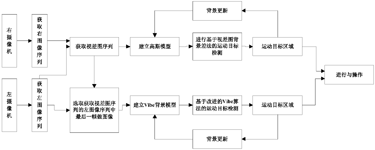
[0046] A kind of moving target detection method based on Vibe and disparity map background difference method of the present invention, its specific operation process is as follows figure 1 As shown, it mainly includes the following two steps S1-S3, and the steps S1-S3 are described in detail below:

[0047] Under the parallel binocular stereo vision system, S1 uses left and right cameras to collect images, and performs motion foreground detection based on the ...


PUM


Abstract

The invention discloses a Vibe and disparity map background subtraction method-based moving target detection method, and relates to the field of computer vision. The method comprises the steps of firstly building a Gaussian model according to a disparity map sequence, and performing moving target detection by adopting a disparity map background subtraction method; secondly performing moving targetdetection based on an improved Vibe algorithm; and finally performing AND operation on two moving target detection results to obtain a final moving target region, continuing to update a background model, and performing moving target detection of the next frame. A monocular vision-based target detection method and a binocular vision-based target detection method are combined; the complete moving target can be extracted; the problem that the monocular vision-based moving target detection is easily influenced by lighting and shadows is improved; and the ghost phenomenon can be eliminated.

Description

technical field [0001] The invention relates to the field of computer vision, in particular to a moving target detection method based on Vibe and disparity map background difference method. Background technique [0002] Moving target detection is the basis of target recognition and tracking. Fast and accurate detection of moving targets is conducive to follow-up work such as target tracking, recognition and behavior understanding. It has a wide range of applications in iris, face recognition, security monitoring, robot navigation, aircraft and satellite monitoring systems, etc. [0003] Among them, there are three kinds of moving target detection algorithms: optical flow method, frame difference method and background difference method. The optical flow method requires special hardware support, and the calculation is complex and computationally intensive, so it is generally seldom used. The principle of the inter-frame difference method is simple, and it is not sensitive to...

Claims


Application Information

Patent Timeline
Patent Type & Authority Applications(China)
IPC IPC(8): G06T7/215G06T5/00G06T7/194
CPCG06T5/006G06T2207/20228G06T7/194G06T7/215
Inventor 陈蓉
Owner HUNAN VISION SPLEND PHOTOELECTRIC TECH
Why Eureka
Try Eureka