
Sewage treatment device

A sewage treatment device and outlet pipe technology, applied in water/sewage treatment equipment, water/sewage treatment, biological water/sewage treatment, etc., can solve the problems of increasing power consumption, reducing the purification effect of microorganisms on sewage, and achieving accelerated separation , Improve efficiency, improve the effect of processing efficiency

Pending Publication Date: 2018-05-18
湖南惟创环境科技有限公司
View PDF0 Cites 0 Cited by
  • Summary
  • Abstract
  • Description
  • Claims
  • Application Information

AI Technical Summary

Problems solved by technology

However, the existing biological contact oxidation tank is a single tank type, which is completely mixed in fluid state. In other words, microorganisms are all in the same reaction tank.
However, in view of the different types of metabolism of microorganisms and the differences in the nutrients consumed by metabolism, it is easy to form survival competition among microorganisms in the same reaction tank, reducing the purification effect of microorganisms on sewage, and the fillers suspended in the biological reaction tank are fixed at high and low settings. On the top of the filler bracket, below the filler is the aeration head or aeration tube. After the aeration head or aeration tube is damaged, due to the blocking of the fixed filler, personnel cannot enter the bottom of the tank for maintenance or replacement. The treatment efficiency of sewage equipment is gradually increasing. Reduce until the equipment is scrapped. In addition, in order to ensure that the sludge concentration in the biological reaction tank will not decrease, the sludge in the sedimentation tank is usually partially refluxed through a return pump, which increases power consumption.

Method used


Image

  • Sewage treatment device
  • Sewage treatment device

Examples


Embodiment Construction

[0037] The present invention will be further described in detail and completely below in conjunction with the embodiments and the accompanying drawings.

[0038] For the convenience of description, spatially relative terms may be used here, such as "on ...", "over ...", "on the surface of ...", "above", etc., to describe the The spatial positional relationship between one device or feature shown and other devices or features. It will be understood that the spatially relative terms are intended to encompass different orientations of the device in use or operation in addition to the orientation depicted in the figures. For example, if the device in the figures is turned over, devices described as "above" or "above" other devices or configurations would then be oriented "beneath" or "above" the other devices or configurations. under other devices or configurations”. Thus, the exemplary term "above" can encompass both an orientation of "above" and "beneath". The device may be o...


PUM


Abstract

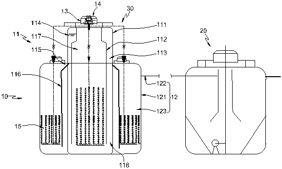
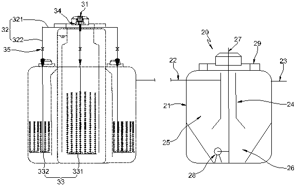
The invention discloses a sewage treatment device, and belongs to the field of environmental treatment equipment. The sewage treatment device comprises a contact oxidation assembly, a precipitation and clarification assembly and an aeration assembly, wherein the contact oxidation assembly is communicated with the precipitation and clarification assembly; the aeration assembly can be driven to be embedded inside the contact oxidation assembly; the contact oxidation assembly comprises an inner reactor and an outer reactor which are arranged coaxially; the outer side of the inner reactor is annularly sleeved with the outer reactor. Through the outer reactor and the inner reactor which are sleeved coaxially and annularly, sewage can only reach the outer reactor through the inner reactor, so that spatial selective allocation of microorganisms at different growth stages with different functions is realized in a plug flow treatment way, the synergistic effect among microbial populations of the same type can be brought into full play, the synergistic effect among different microbial populations is overcome, and the treatment efficiency is improved remarkably.

Description

technical field [0001] The invention relates to a sewage treatment device, in particular to a sewage treatment equipment which facilitates biological contact oxidation reaction, and belongs to the field of environmental treatment equipment. Background technique [0002] As the difference between urban and rural areas in our country becomes more and more obvious, for cities with a relatively concentrated population, centralized sewage treatment can solve the problem of urban domestic sewage well. However, most of the rural areas are sparsely populated, and many places cannot lay sewage pipe networks due to huge pipeline network investment or terrain problems, resulting in a large amount of domestic sewage being discharged directly without any treatment, which is likely to cause serious water pollution. Therefore, decentralized sewage treatment equipment plays an important role in the treatment of sewage in rural areas, and small and medium-sized buried sewage treatment equipm...

Claims


Application Information

Patent Timeline
IPC IPC(8): C02F9/14C02F101/16
CPCC02F3/302C02F3/34C02F2303/14C02F2201/007C02F2001/007C02F2101/16
Inventor 汪浏阳田芸张春红刘富安赵会芳
Owner 湖南惟创环境科技有限公司
Learn More