Structure capable of improving thermal performance of under-window wall and method for improving thermal performance of under-window wall

A technology of thermal performance and inner wall, applied in building components, building structure, building maintenance, etc., can solve the problems of large heat transfer coefficient of wall and heat loss, etc., to achieve simple and easy construction, energy saving, increase heat The effect of utilization and room temperature

Pending Publication Date: 2018-05-18
HARBIN INST OF TECH
View PDF4 Cites 0 Cited by
  • Summary
  • Abstract
  • Description
  • Claims
  • Application Information

AI Technical Summary

Problems solved by technology

[0003] The present invention aims to solve the problem that the heat transfer coefficient of the lower part of the window sill is too large and heat loss is easily generated, and now provides a structure and method that can improve the thermal performance of the lower wall of the window

Method used


Image

  • Structure capable of improving thermal performance of under-window wall and method for improving thermal performance of under-window wall
  • Structure capable of improving thermal performance of under-window wall and method for improving thermal performance of under-window wall

Examples


specific Embodiment approach 1

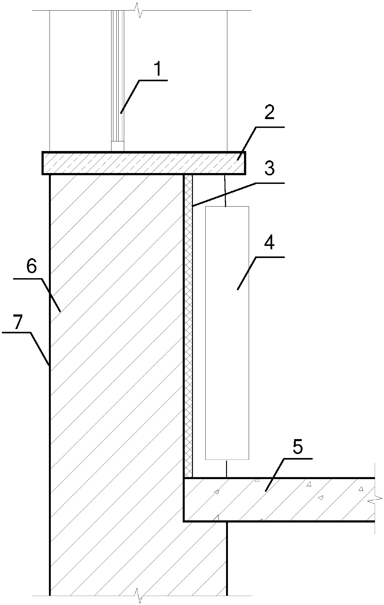
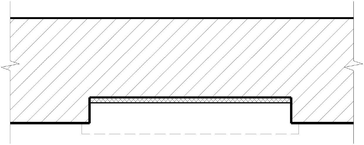
[0016] Specific implementation mode one: refer to figure 1 and figure 2 Describe this embodiment in detail. This embodiment is a structure that can improve the thermal performance of the wall under the window for the purpose of preventing heat from being lost to the outside and at the same time reflecting the heat generated by the radiator to the room. The structure is specifically:

[0017] The wall below the window is in order from outside to inside: exterior finish, 370mm thick solid brick wall, leveling layer, insulation layer, moisture-proof layer and aluminum foil reflection layer, and the layers are pasted and fixed to each other.

[0018] The structure that can improve the thermal performance of the wall under the window described in this embodiment, under the premise of ensuring that the structural form of the existing public building remains unchanged, the part of the wall under the window is treated indoors, and high-efficiency plate insulation materials are added ...

specific Embodiment approach 2

[0019] Specific implementation mode 2: This implementation mode is a method for improving the thermal performance of the wall under the window for the purpose of preventing heat from being lost to the outside and at the same time reflecting the heat generated by the radiator to the room. The specific method is as follows:

[0020] Step 1: In order to ensure the smoothness and firmness of the thermal insulation material, it is necessary to clean and repair the original base wall, remove the dust, loose matter and other substances on the wall that affect the attachment, and then use cement mortar to clean the wall under the window. The inner side is repaired to make the wall level and form a leveling layer.

[0021] Step 2: In order to increase the thermal resistance of the wall under the window, improve the thermal insulation performance of this part, and reduce the loss of indoor heat to the outside. EPS boards (molded polystyrene foam boards), XPS boards (extruded polystyrene...


PUM


Abstract

The invention provides a structure capable of improving thermal performance of an under-window wall and a method for improving thermal performance of the under-window wall, relates to the field of construction, and aims to solve the problem that the heat transfer coefficient of a wall body under a window is too large and loss of heat is easily produced. According to the structure and the method disclosed by the invention, the inner sides of the under-window wall are cleared up, and then the inner sides of the under-window wall are repaired by utilizing cement mortar to enable a wall surface tobe flat so as to form a leveling layer; a heat insulation board is adhered in the leveling layer to form a heat insulation layer; a moisture-proof layer is arranged in the inner side of the heat insulation layer; aluminum foil is adhered to the inner side of the moisture-proof layer by adopting an adhesive so as to form an aluminum foil reflecting layer. The structure and the method disclosed bythe invention are suitable for being used in severe cold regions, and heat insulation treatment on under-window walls of public buildings is achieved.

Description

technical field [0001] The invention belongs to the field of construction, and in particular relates to a thermal insulation structure of a wall under a window. Background technique [0002] The heating method of public buildings in severe cold areas is mostly the centralized heating of urban pipe networks, and the interior of the building obtains heat through the heat dissipation of radiators. The exterior walls of public buildings in the early construction period are mainly 490mm solid brick walls. In order to facilitate the installation of radiators and the integrity and aesthetics of the interior space, a 120mm thick space is usually reserved on the lower part of the window sill to install radiators. That is, the thickness of the wall under the window is 370mm. This structure will cause the wall at this part to be thinner than the main body of the exterior wall, resulting in poor thermal performance. It will become one of the weak parts of exterior wall insulation and e...

Claims


Application Information

Patent Timeline
Patent Type & Authority Applications(China)
IPC IPC(8): E04G23/02E04B1/76E04B1/80E04B1/66
CPCE04B1/665E04B1/7625E04B1/80E04G23/02E04G23/0296
Inventor 金虹康健邵腾陈德龙金雨蒙
Owner HARBIN INST OF TECH
Why Eureka
Try Eureka