
Multi-degree-of-freedom adjusting pan-tilt for handheld laser range finder calibration

A laser rangefinder and hand-held technology, which is applied in the field of geometric measuring device verification devices, can solve the problems of no positioning and adjustment devices for hand-held laser rangefinders, and achieve the effects of easy operation, vibration elimination, and reasonable structure

Pending Publication Date: 2018-05-18
TIANJIN INST OF METROLOGICAL SUPERVISION & TESTING
View PDF0 Cites 3 Cited by
  • Summary
  • Abstract
  • Description
  • Claims
  • Application Information

AI Technical Summary

Problems solved by technology

[0009] In the current domestic and foreign markets, there is no special device for the positioning and adjustment of the handheld laser rangefinder.

Method used


Image

  • Multi-degree-of-freedom adjusting pan-tilt for handheld laser range finder calibration
  • Multi-degree-of-freedom adjusting pan-tilt for handheld laser range finder calibration
  • Multi-degree-of-freedom adjusting pan-tilt for handheld laser range finder calibration

Examples


Embodiment Construction

[0026] Error analysis of multi-degree-of-freedom adjustment pan-tilt for verification of a hand-held laser rangefinder

[0027] 1. Necessity analysis of multi-degree-of-freedom adjustment:

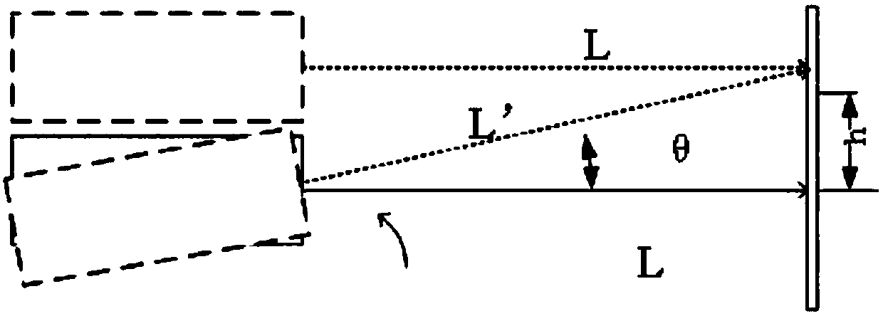
[0028] like figure 2 As shown, in the process of adjusting the position of the spot on the reflector to move along the z-axis direction, when the hand-held laser rangefinder uses two methods of translation and pitch to adjust the spot displacement to h, the actual optical path lengths are L and L', and when the angular displacement is θ, the optical path difference e introduced by the pitch adjustment method is

[0029]

[0030] θ=arctanh / L (3-2)

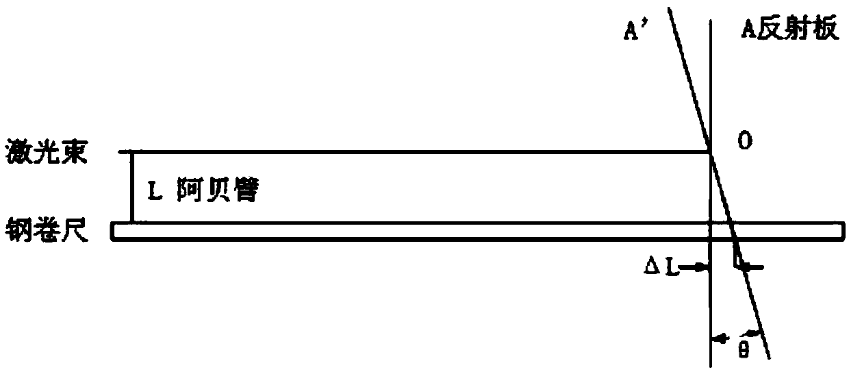
[0031] Verify the optical path difference introduced by the pitch adjustment, and calculate the pitch angle θ that needs to be adjusted for the spot moving distance h when L=1m, 1.5m, 2m, and 20m, and obtain the pitch angle θ and the theoretical optical path difference e, and the measured optical path The difference e' is shown in Table 2...


PUM


Abstract

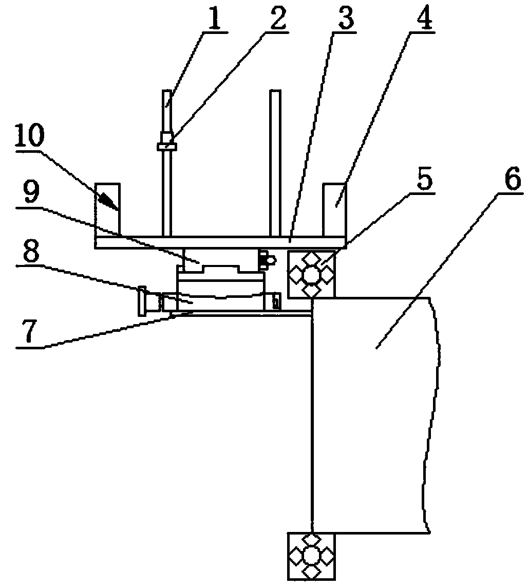
The invention belongs to the technical field of geometric measurement device calibrating devices, and relates to a laser range finder calibration, in particular to a multi-degree-of-freedom adjustingpan-tilt for handheld laser range finder calibration. The pan-tilt comprises a fixing table, a clamping device is installed at one end of the fixing table, the clamping device is used for being fixedto one end of a calibrating table, a manual angular displacement table is installed inside the fixing table, a manual rotating table is fixedly installed above the manual angular displacement table, afixing base is installed above the manual rotating table, the fixing base is used for containing a handheld laser range finder to be calibrated, and under the state of containing the handheld laser range finder, the laser emitting direction of the handheld laser range finder and the extending direction of a calibration table extend in parallel; the fixing base comprises a base plate, the upper end face of the base plate is arranged flatly, and the side, close to the calibration table and the side, back onto the calibration table, of the base plate are each vertically provided with a datum plate.

Description

technical field [0001] The invention belongs to the technical field of verification devices for geometric measuring devices, and relates to a verification device for a laser range finder, in particular to a multi-degree-of-freedom adjustment platform for verification of a handheld laser range finder. Background technique [0002] In the process of measurement and detection of length geometric quantities, there is a common problem of correctness of information sources. The unsatisfactory relative measurement position between the measurement standard and the measured element is one of the typical situations that affect the correctness of the information source, introducing additional errors into the system and affecting the accuracy of the verification results. [0003] Taking the marble test table with a total length of 50.423m and a width of 124.23mm as an example, its upper surface and one side surface are the standard working surfaces. The theoretical precision of the marb...

Claims


Application Information

Patent Timeline
Patent Type & Authority Applications(China)
IPC IPC(8): G01C25/00
CPCG01C25/00
Inventor 路瑞军刘红光李元耀
Owner TIANJIN INST OF METROLOGICAL SUPERVISION & TESTING
Learn More