
Recognition device for test tube

A technology for identifying devices and test tubes, which is applied in the direction of test tube holders/clamps, instruments, and induction recording carriers, etc., which can solve problems such as time-consuming, large-scale application impact, and large standard differences, so as to avoid misoperation, improve detection efficiency, and automate degree, the effect of less manual intervention

Pending Publication Date: 2018-05-18
ANPAC BIO MEDICAL SCI (LISHUI) CO LTD
View PDF0 Cites 4 Cited by
  • Summary
  • Abstract
  • Description
  • Claims
  • Application Information

AI Technical Summary

Problems solved by technology

This method is time-consuming, labor-intensive, and has large errors, which will easily cause the testing center to stagnate for a long time, and because it relies on manual work, the standards vary greatly, and at the same time, it needs to increase the time and cost of training, etc., which has a profound impact on large-scale applications.

Method used


Image

  • Recognition device for test tube

Examples


Embodiment Construction

[0029] The advantages of the present invention will be further elaborated below in conjunction with the accompanying drawings and specific embodiments.

[0030] Reference will now be made in detail to the exemplary embodiments, examples of which are illustrated in the accompanying drawings. When the following description refers to the accompanying drawings, the same numerals in different drawings refer to the same or similar elements unless otherwise indicated. The implementations described in the following exemplary examples do not represent all implementations consistent with the present disclosure. Rather, they are merely examples of apparatuses and methods consistent with aspects of the present disclosure as recited in the appended claims.

[0031] It should be understood that although the terms first, second, third, etc. may be used in the present disclosure to describe various information, the information should not be limited to these terms. These terms are only used ...


PUM


Abstract

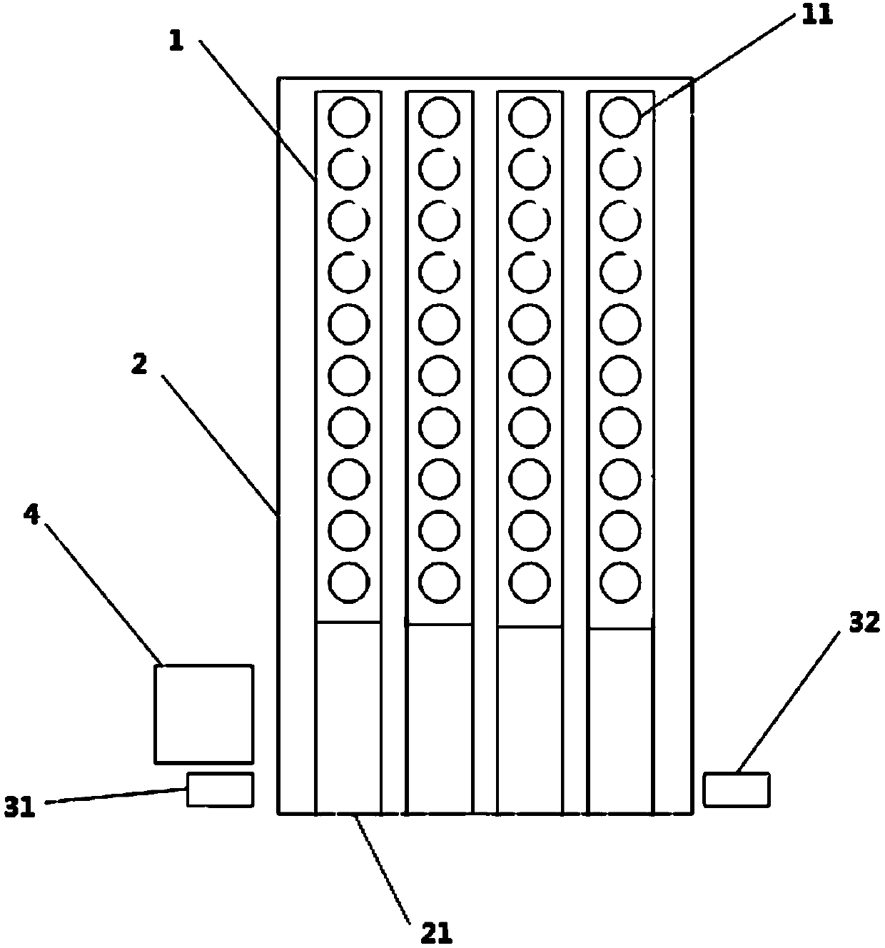
The invention provides a recognition device for a test tube. The recognition device comprises at least one test tube, at least one test tube rack, and a scanner. The test tube rack comprises at leastone test tube accommodating part. The recognition device is characterized by also comprising a test tube detection position assembly and a group of optical fiber detection facilities. The test tube detection position assembly comprises at least one group of test tube position modules. The recognition device also comprises a control module. The control module is electrically connected to the optical fiber detection facilities, the test tube position modules, and the scanner. When the test tube rack is pushed along a slot, the test tube rack is completely stored in the test tube detection position assembly, and based on the electric property judging label and the position information of the test tube, correlation between the position information and the memory information is established andstored. The test tube detection efficiency and automation degree are improved.

Description

technical field [0001] The invention relates to the field of biotechnology equipment, in particular to an identification device for test tubes. Background technique [0002] With the rapid development of automatic biochemical testing equipment, one piece of equipment can accommodate dozens or even hundreds of test tube samples for sequential testing. For these test tubes, identification needs to be set so that the detection equipment can access the test tubes and the position information of the test tubes. Relying on manual storage of this information will bring about a series of problems such as heavy workload, missed input, repeated input, long time consumption, and low efficiency. [0003] Generally, the traditional method is to manually scan the barcode on the test tube with a hand-held scanning gun to input the information into the testing device, and then put the test tube into the detection position of the device to be checked. This method is time-consuming, labor-i...

Claims


Application Information

Patent Timeline
Patent Type & Authority Applications(China)
IPC IPC(8): G06K7/10B01L9/06
CPCG06K7/10861B01L9/06B01L2300/021
Inventor 赵荣春
Owner ANPAC BIO MEDICAL SCI (LISHUI) CO LTD
Learn More