
A guardrail punching device

A technology of punching device and guardrail, which is applied in the direction of feeding device, positioning device, peeling device, etc., can solve the problems of low punching efficiency and bending guardrail.

Active Publication Date: 2019-04-26
山东宏阳型材科技股份有限公司
View PDF7 Cites 0 Cited by
  • Summary
  • Abstract
  • Description
  • Claims
  • Application Information

AI Technical Summary

Problems solved by technology

[0005] The purpose of the present invention is to provide a guardrail punching device to solve the problem that the punching efficiency of the guardrail punching device in the prior art is low, and the guardrail is likely to be bent during the punching process

Method used


Image

  • A guardrail punching device
  • A guardrail punching device
  • A guardrail punching device

Examples


Embodiment Construction

[0019] The present invention will be described in further detail below by means of specific embodiments:

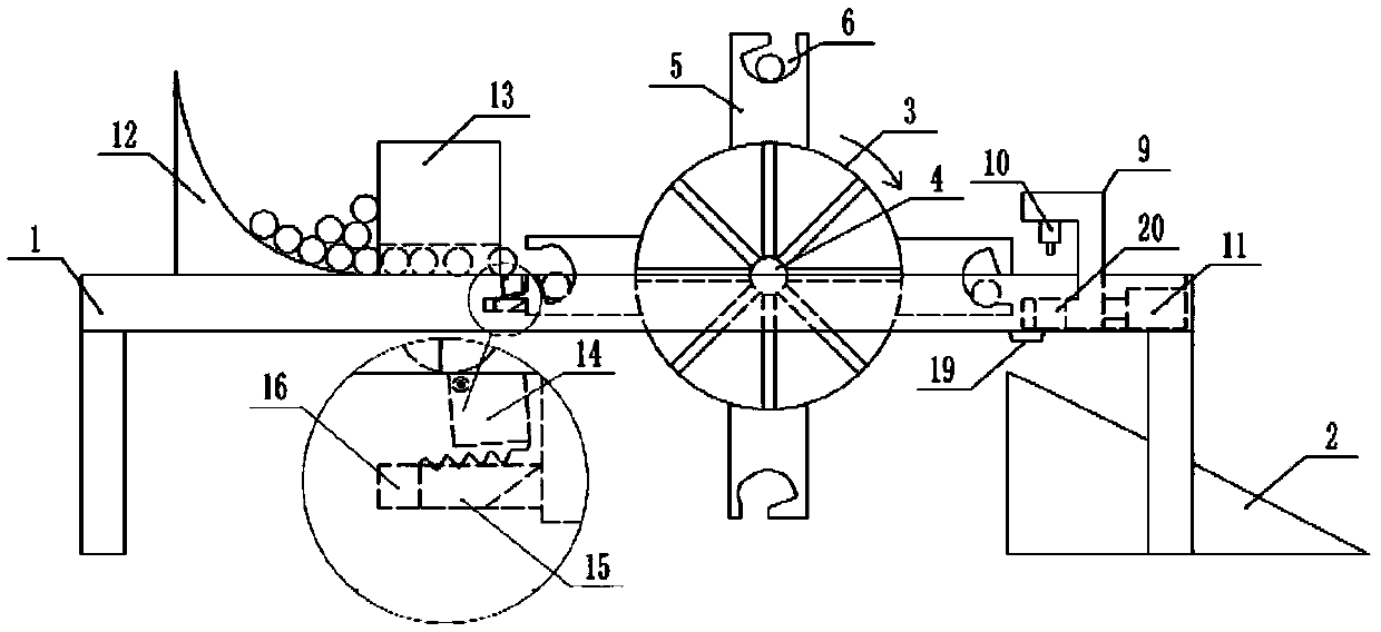
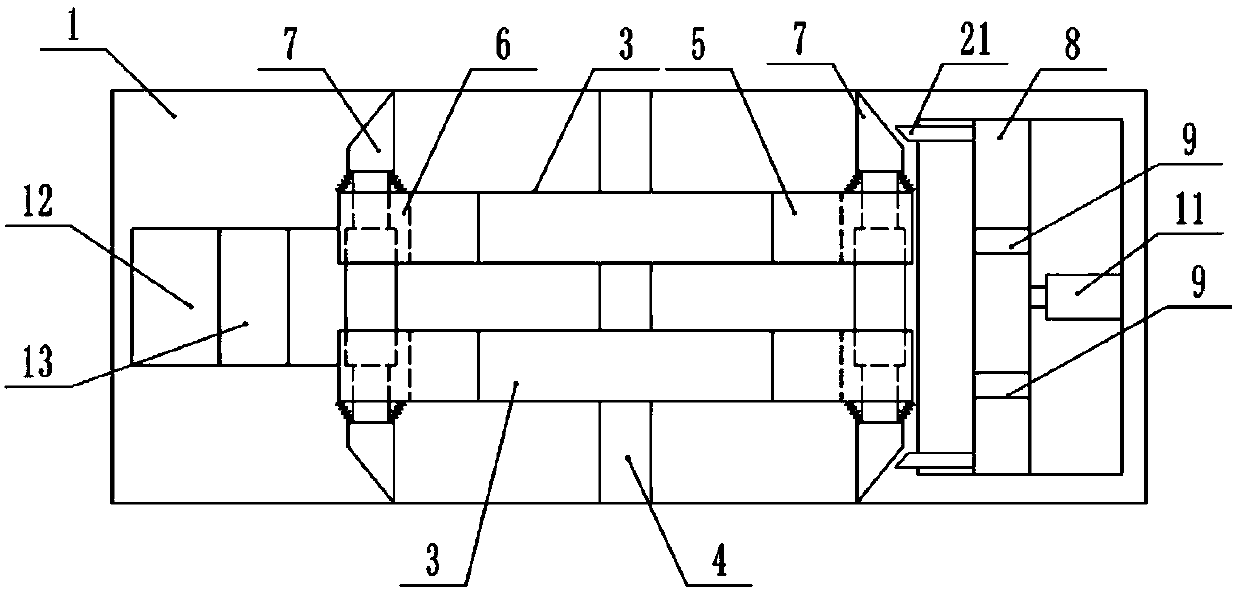
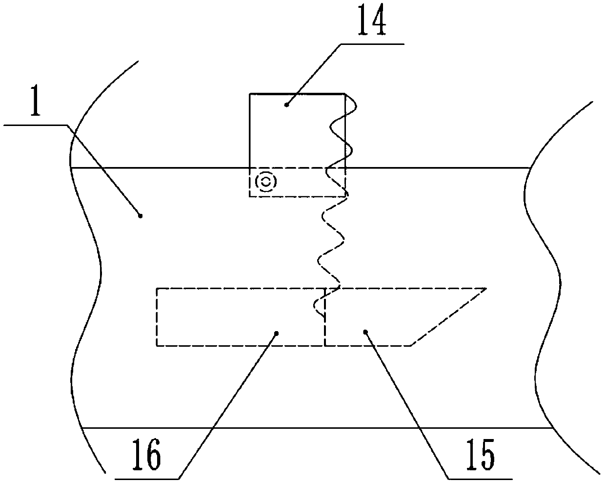
[0020] The reference signs in the drawings of the description include: bracket 1, discharge block 2, rotating wheel 3, rotating shaft 4, strut 5, groove 6, first wedge block 7, first sliding block 8, mounting seat 9, Vertical cylinder 10, horizontal cylinder 11, arc seat 12, cavity seat 13, rotating block 14, second slide block 15, second chute 16, elastic part 17, clamping part 18, debris outlet 19, center Hole 20, second wedge block 21.

[0021] Such as figure 1 and figure 2 As shown, a guardrail punching device includes a bracket 1, and the bracket 1 is sequentially provided with a feeding part, a material limiting mechanism, a transmission mechanism and a punching mechanism from left to right, and a discharge block 2 is arranged below the punching mechanism. The guardrail of punching holes is sent out through the discharge block 2, and the transmission mechanism i...


PUM


Abstract

The invention belongs to the technical field of guard bar machining and particularly discloses a guard bar punching device. The guard bar punching device comprises a support; the support is sequentially provided with a feeding portion, a limiting mechanism, a conveying mechanism and a punching mechanism; a discharging block is disposed below the punching mechanism; the conveying mechanism comprises a motor, a rotary shaft and two rotary wheels; extending-out supporting rods are disposed on the rotary wheels and provided with grooves used for bearing guard bars; first wedge-shaped blocks are connected into the grooves in a sliding mode; the punching mechanism comprises a first sliding block, a mounting seat, a vertical air cylinder and a horizontal air cylinder; second wedge-shaped blocks are disposed on the two sides of the first sliding block; the vertical air cylinder is fixedly connected to the mounting seat; the horizontal air cylinder is fixedly connected to the support; and a piston rod of the horizontal air cylinder is fixedly connected with the first sliding block. According to the guard bar punching device, the punching efficiency is high, and the guard bars are not bent during punching.

Description

technical field [0001] The invention belongs to the technical field of guardrail processing, and specifically discloses a guardrail punching device. Background technique [0002] Guardrails are mainly used in residences, highways, commercial areas and other public places for protection and isolation. During the processing of the guardrail, it is necessary to punch the guardrail to facilitate its connection with the column. At present, guardrail processing factories mostly use bench drills to punch guardrails, and the punching efficiency is low. [0003] In order to solve the above-mentioned technical problems, the application publication number is CN107282969A Chinese invention patent application discloses a guardrail punching device, including a feeding part, a workbench, an electric drill, a drill bit, a mounting seat, a horizontal cylinder, a stand, a clamping device, a vertical Straight cylinder and push plate, the workbench is fixed above the feeding part through bolt...

Claims


Application Information

Patent Timeline
Patent Type & Authority Patents(China)
IPC IPC(8): B21D28/24B21D43/20B21D43/14B21D43/00B21D45/06
CPCB21D28/24B21D43/003B21D43/14B21D43/20B21D45/06
Inventor 周强周琪
Owner 山东宏阳型材科技股份有限公司
Learn More