Coordinate measuring device comprising an optical sensor, and corresponding method

A coordinate measurement and sensor technology, applied in the field of optical measurement of gear workpieces, to achieve the effect of fast gear measurement and accurate cost

Active Publication Date: 2018-05-25
KLINGELNBERG AG
View PDF10 Cites 3 Cited by
  • Summary
  • Abstract
  • Description
  • Claims
  • Application Information

AI Technical Summary

Problems solved by technology

However, at steep scan angles, the sensor will not pick up a useful signal

Method used


Image

  • Coordinate measuring device comprising an optical sensor, and corresponding method
  • Coordinate measuring device comprising an optical sensor, and corresponding method
  • Coordinate measuring device comprising an optical sensor, and corresponding method

Examples


Embodiment Construction

[0051] In the context of this description, terms that are also used in related publications and patents are used. However, it should be noted that these terms are used only to provide better understanding. The inventive concept and protection scope of the patent claims are not limited by the specific choice of terms. The invention can be readily applied to other conceptual systems and / or subject areas. In other subject areas, these terms will apply mutatis mutandis.

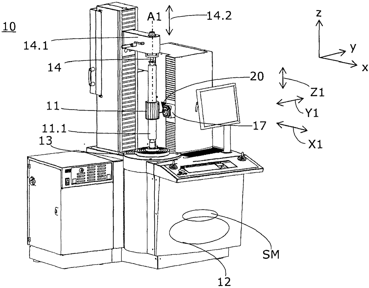
[0052] exist figure 1 An advantageous embodiment of the invention shown in , relates to an automated CNC-controlled gear measuring center 10 generally referred to herein as a coordinate measuring device 10 . The coordinate measuring device 10 is in principle suitable for checking general dimensional, shape and positional deviations on spur gear teeth as well as cutting and grinding wheels, worms and worm gears, hobs, bevel gears and rotationally symmetrical workpieces for bending and camshaft measurements or ...


PUM


Abstract

The invention relates to a coordinate measuring device comprising an optical sensor, and a corresponding method. The coordinate measuring device (10) has a rotatably drivable receptacle (13, 14) for agear component (11) to be measured, a measuring assembly (17) and a plurality of axes (X1, Y1, Z1, A1), which are adapted to feed movements and measuring movements of the measuring assembly (17) relative to the gear component (11), wherein the measuring assembly comprises: an optical switching sensor (20) which operates in a non-contact mode and is designed as a focus trigger sensor, wherein thefocus trigger sensor is arranged on the measuring assembly so that it is able to emit a light beam (LS) along an optical axis in the direction of the gear component (11), the focus trigger sensor is executable relative to the scanning movements of the gear component (11) through using one or more axis focus trigger sensors of the axes (X1, Y1, Z1, A1), and when the gear component (11) reaches thenominal distance (NA) relative to the focus trigger sensor, it is always provided with a switching signal (s2) provided by the focus trigger sensor.

Description

technical field [0001] The invention relates to a coordinate measuring device with an optical sensor and a corresponding method for optically measuring gear workpieces. Background technique [0002] Accurate measurement of components is very important in many technical fields. [0003] For example, there are various measurement devices for tactile detection of the quality and profile of surfaces. Typically, the probe tip is guided onto the surface to be measured during mechanical scanning. The result is a recorded signal on the scan path which allows statements about the surface profile. [0004] During the production process, such measurements need to be performed as consistently as possible, where the mentioned mechanical scanning is very precise, but unfortunately also rather slow. For integration into production processes, mechanical measurements are therefore not suitable in most cases. Today, mechanical scanning methods are therefore used, for example, to test indi...

Claims


Application Information

Patent Timeline
IPC IPC(8): G01B11/00
CPCG01B11/005G01B11/007G01B11/2416G01B11/26
Inventor G·米斯
Owner KLINGELNBERG AG
Why Eureka
Try Eureka