Power battery top cover structure and power battery

A power battery and top cover technology, which is applied to small-sized batteries/battery packs, battery covers/end covers, batteries, etc., and can solve the problems of inability to fuse connecting parts, short-circuit parts easily melted, and too low current.

Active Publication Date: 2021-05-07
CONTEMPORARY AMPEREX TECH CO
View PDF9 Cites 0 Cited by
  • Summary
  • Abstract
  • Description
  • Claims
  • Application Information

AI Technical Summary

Problems solved by technology

However, if the positive and negative poles are directly connected and short-circuited, because the resistance in the loop is too small, the current in the loop will be too large (for example, more than 10000A), and the short-circuit part will be easily melted, and the short-circuit part will be fused before the connecting part is fused If it is dropped, the loop current disappears, and the connecting parts cannot be fused; but if the resistance in the loop is too large, the current in the loop will be too small (for example, less than 500A), the connecting parts will not be fused, and the power to stop cannot be achieved. The role of the battery to continue charging, so when dealing with the overcharge of the power battery, it is obviously impossible to directly reduce the current by connecting a large resistor

Method used


Image

  • Power battery top cover structure and power battery
  • Power battery top cover structure and power battery
  • Power battery top cover structure and power battery

Examples


Embodiment Construction

[0114] The present application will be described in further detail below through specific embodiments and in conjunction with the accompanying drawings. The "front", "rear", "left", "right", "upper" and "lower" mentioned in the text are all referred to the power battery top cover structure in the attached drawings.

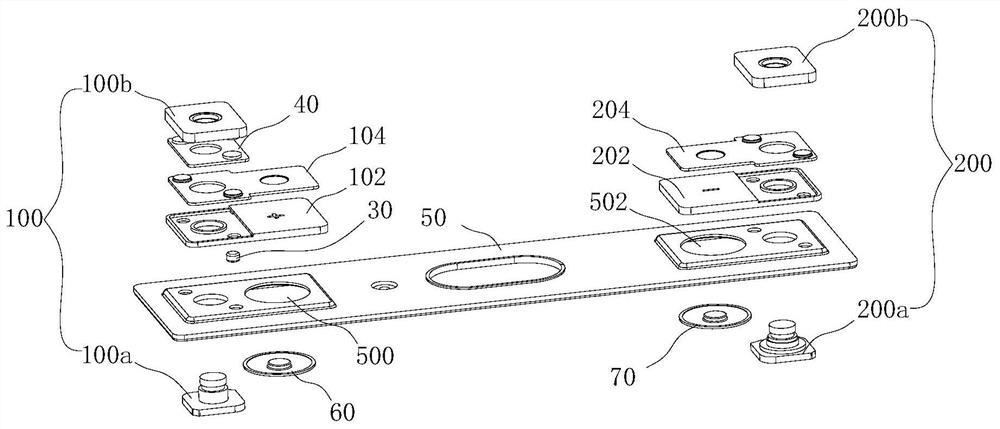
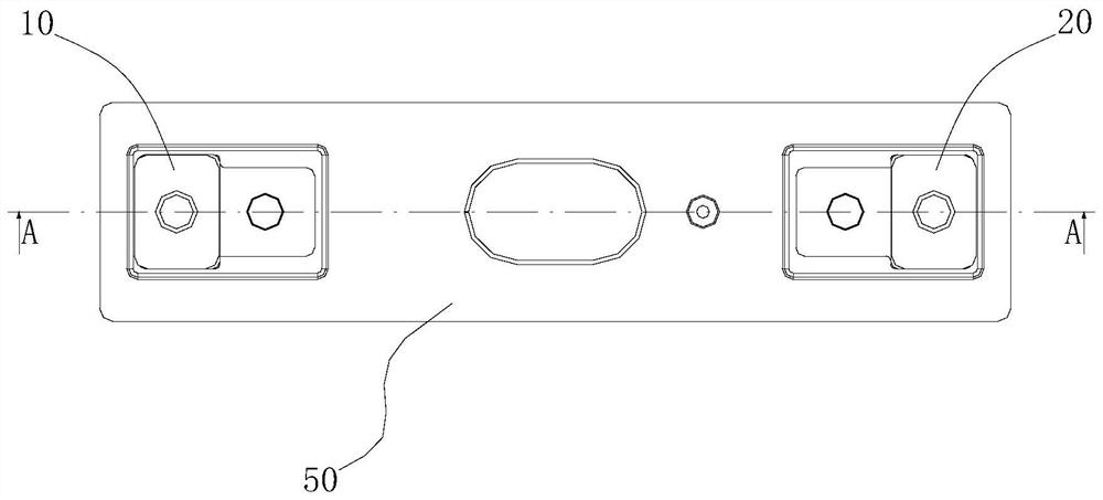
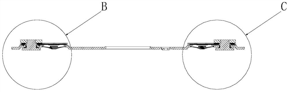
[0115] The embodiment of the present application provides a power battery, such as Figure 17 As shown, it includes a power battery top cover structure 1, a bare cell 2, a casing 3, a first connector 4, and a second connector 5. The bare cell 2 is usually composed of a positive electrode sheet, a negative electrode sheet, and a separator through winding or lamination. Formed, the positive electrode tab 2a and the negative electrode tab 2b are respectively drawn out on the positive electrode sheet and the negative electrode sheet. The shell 3 is generally made of metal, and together with the top cover structure 1 of the power battery, forms a cavity for accommodat...


PUM

PropertyMeasurementUnit
electrical resistanceaaaaaaaaaa

Abstract

The present application relates to the field of energy storage devices, in particular to a power battery top cover structure, including a first electrode assembly, a second electrode assembly, a first resistor, a second resistor, a top cover sheet, a first short-circuit component and a second short-circuit component , the first electrode assembly and the top cover sheet are always electrically connected through the first resistor, the first short circuit part and the second short circuit part are attached to the top cover sheet, when the internal pressure of the power battery exceeds the reference pressure, the first short circuit part and the second short circuit part The short-circuit component can act under pressure to form a first electrical connection path and a second electrical connection path, and the second resistor is connected in series in the first electrical connection path. The power battery includes a bare cell and a top cover structure of the power battery. After the first short-circuit component and the second short-circuit component operate, a first electrical connection loop and a second electrical connection loop can be formed. The top cover structure of the power battery provided by the embodiment of the present application can enable the power battery to form a circuit with a suitable resistance value under the conditions of nail penetration and overcharging respectively.

Description

technical field [0001] The present application relates to the field of energy storage devices, in particular to a power battery top cover structure and a power battery. Background technique [0002] Electric vehicles and energy storage power stations generally need to use large-capacity power batteries as power sources. In addition to high capacity, these power batteries should also have good safety and long cycle life, so as to meet the standards of use and meet people's needs. [0003] In the prior art, when the power battery is overcharged, the decomposition of the electrolyte of the power battery will cause excessive heat inside the power battery and cause the battery to catch fire, or increase the internal pressure of the power battery and cause the battery to explode (as long as the power battery does not stop charging , the internal pressure will increase until an explosion occurs). Therefore, before the power battery goes out of control, it is necessary to cut off ...

Claims


Application Information

Patent Timeline
Patent Type & Authority Patents(China)
IPC IPC(8): H01M50/578H01M50/583H01M50/15H01M50/147H01M50/55H01M50/553H01M50/572H01M50/574H01M50/588
CPCH01M50/147H01M50/578H01M50/574H01M50/553H01M50/588H01M50/55H01M2200/20Y02E60/10H01M50/325H01M2220/20
Inventor 王志宇王鹏蔡如来陈柏松
Owner CONTEMPORARY AMPEREX TECH CO
Why Eureka
Try Eureka