Garden pruning robot
A robot and gardening technology, applied in the field of intelligent robots, can solve problems such as waste of labor, time-consuming, and poor pruning effects, and achieve the effects of improving travel efficiency, high work efficiency, and good work results
- Summary
- Abstract
- Description
- Claims
- Application Information
AI Technical Summary
Problems solved by technology
Method used
Image
Examples
Embodiment 1
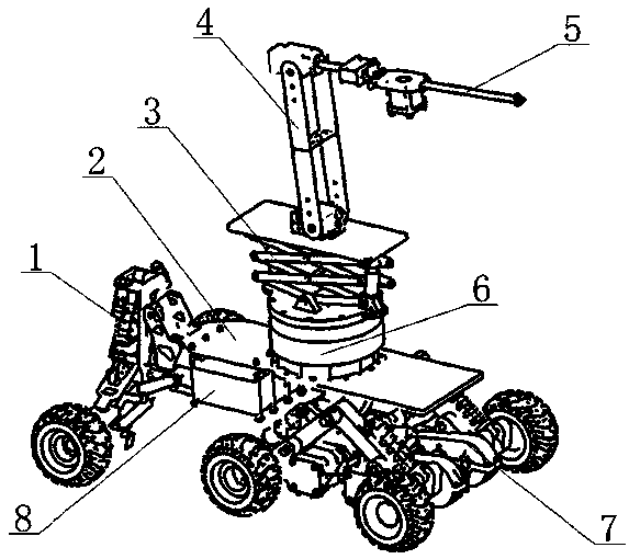
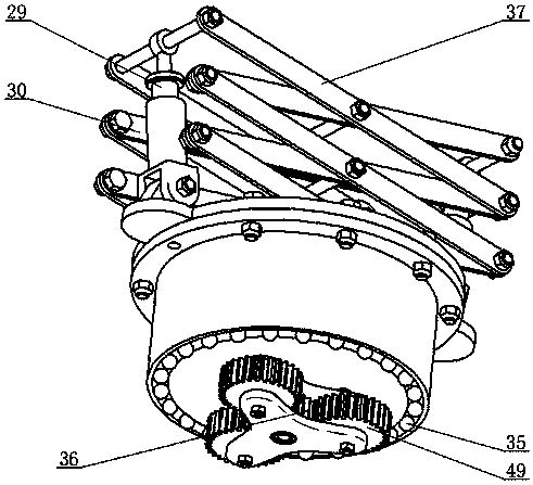
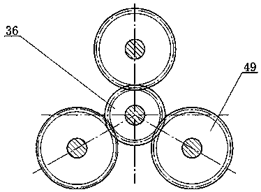
[0035] Embodiment 1: as Figure 1-5 , shown in 8-13, this pruning garden robot comprises steering mechanism 1, vehicle frame 2, elevating mechanism 3, pruning mechanical arm 4, pruning tool 5, planetary rotating mechanism 6, driving device 7, storage battery 8; Wherein steering mechanism 1 installs In front of the vehicle frame 2, the storage battery 8 is installed on the vehicle frame 2 front bottom, the driving device 7 is installed on the vehicle frame 2, the rear bottom, the planetary rotation mechanism 6 is installed on the vehicle frame 2, and the elevating mechanism 3 is installed on the planetary rotation mechanism 6. The mechanical arm 4 is installed on the lifting mechanism 3, and the pruning cutter 5 is installed on the pruning mechanical arm 4;
[0036]The steering mechanism 1 includes two front axles 9, a bogie 10, a steering gear 11, two shock absorbers I12, two steering links I13, two front wheels 14, two steering links II15, and two Front wheel axle frame 16, ...
Embodiment 2
[0041] Embodiment 2: as Figure 5-7 As shown, the device structure of this embodiment is the same as that of Embodiment 1, except that the driver 23 includes a drive wheel 18, a shock absorber II 19, a reduction box 22, a drive motor I 24, and a drive wheel frame 25; the reduction box 22 is installed on the drive wheel frame 25- side, the driving motor I24 is installed on the driving wheel frame 25, the output shaft of the driving motor I24 is connected to the input end of the reduction box 22, and the driving wheel 18 is connected to the output end of the reduction box 22 and arranged on the other side of the driving wheel frame 25, driving The wheel frame 25 is hinged on the drive frame 20 , one end of the shock absorber II 19 is fixed on the drive frame 20 , and the other end is hinged to the drive wheel frame 25 .
PUM
 Abstract
Description
Claims
Application Information
 - R&D
- Intellectual Property
- Life Sciences
- Materials
- Tech Scout
- Unparalleled Data Quality
- Higher Quality Content
- 60% Fewer Hallucinations
Browse by: Latest US Patents, China's latest patents, Technical Efficacy Thesaurus, Application Domain, Technology Topic, Popular Technical Reports.
© 2025 PatSnap. All rights reserved.Legal|Privacy policy|Modern Slavery Act Transparency Statement|Sitemap|About US| Contact US: help@patsnap.com


