Compound cylinder for controlling lifting of winding cradleofspinning machine

A technology for spinning machines and cylinders, which is applied in spinning machines, continuous winding spinning machines, textiles and papermaking, etc. It can solve the problems of not ensuring the tightness of yarns, reducing the operating efficiency of machines, and poor working performance. Stability and other issues, to achieve the effect of moderate degree of tightness, high working stability and reasonable structural design

Inactive Publication Date: 2018-05-29
SHAANXI BAOCHENG AVIATION INSTR
View PDF6 Cites 1 Cited by
  • Summary
  • Abstract
  • Description
  • Claims
  • Application Information

AI Technical Summary

Problems solved by technology

However, the lifting action of the winding cradle depends on the drive of the corresponding device. The existing device for controlling the lifting action cannot ensure the tightness of the yarn well, and the work performance is unstable. Breakage often occurs during the winding process. Yarn phenomenon, reducing the efficiency of machine operation

Method used


Image

  • Compound cylinder for controlling lifting of winding cradleofspinning machine
  • Compound cylinder for controlling lifting of winding cradleofspinning machine

Examples


Embodiment Construction

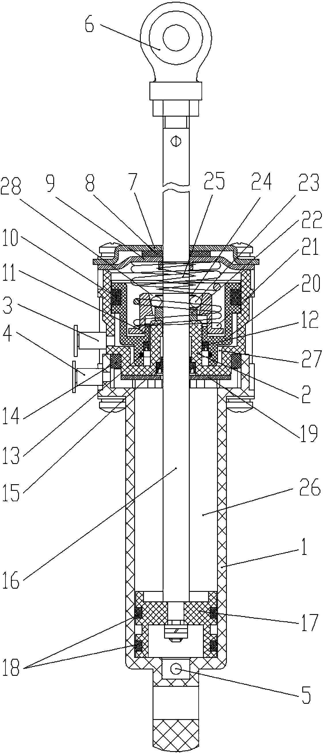
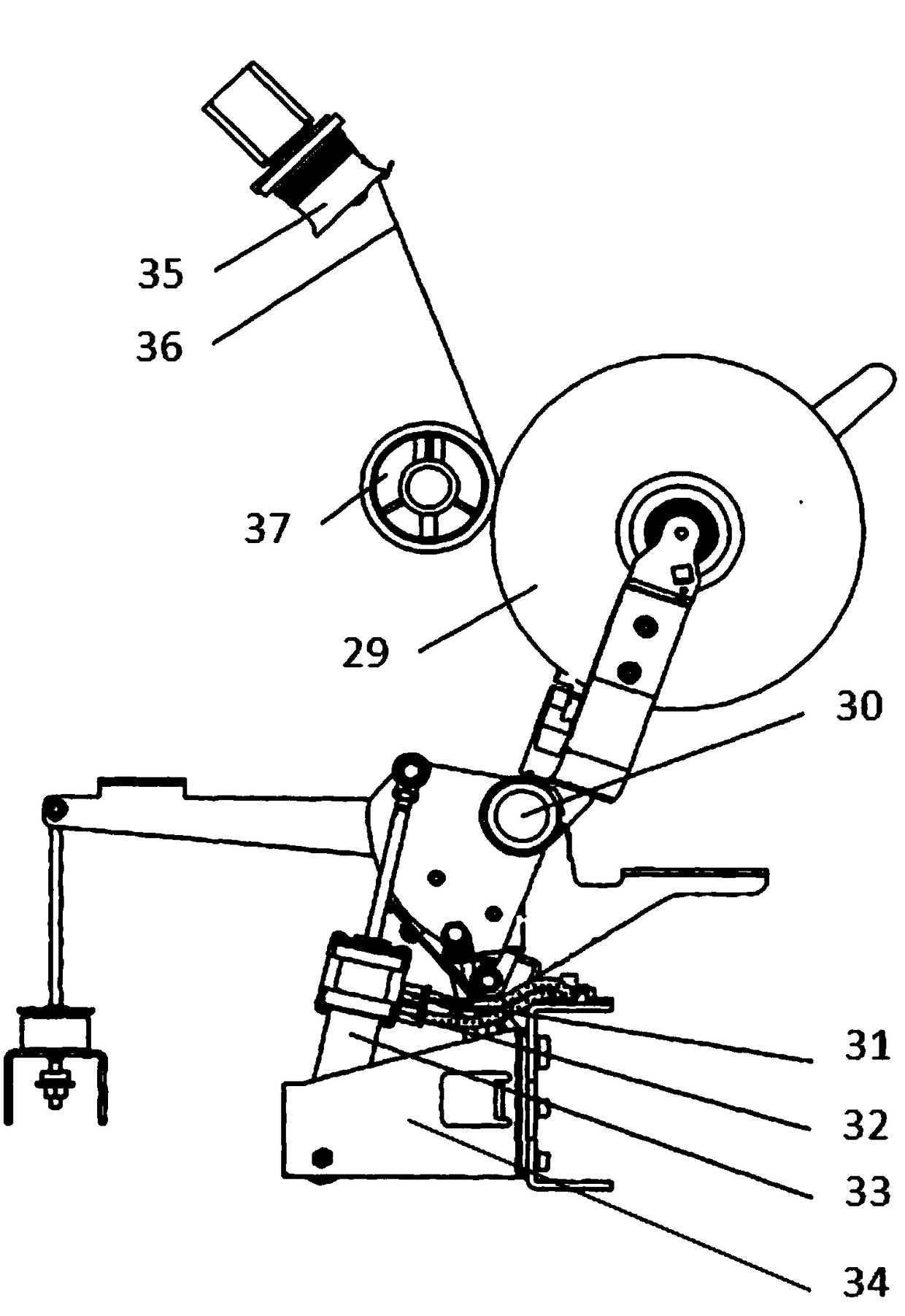
[0017] Attached below Figure 1-2 Embodiments of the present invention are described.

[0018] Composite cylinders used to control the lifting of the winding cradle of spinning machines, such as figure 1 As shown, it includes a large cylinder 1, a small cylinder 2 and a piston rod 16. The bottom of the large cylinder 1 is provided with a muffler 5, and the upper end of the large cylinder 1 is sealed with the lower end of the small cylinder 2. Wherein, the large cylinder The upper end of 1 and the lower end of small cylinder 2 are provided with gasket I19, and the upper end of large cylinder 1 and the lower end of small cylinder 2 are sealed and connected by Y-shaped sealing ring III14, so that the inner cavity of large cylinder 1 and the inner cavity of small cylinder 2 are not connected to each other . The upper end of the small cylinder 2 is covered by a gland plate assembly, specifically, the gland plate assembly includes a pressure plate 7 and a cover plate 9, the cover ...


PUM


Abstract

Provided is a compound cylinder for controlling lifting of a winding cradleof a spinning machine. The spinning machine comprises a large air cylinder, a small air cylinder and a piston rod, the upperend of the large air cylinder and the lower end of the small air cylinder areconnected in a sealing mode,the upper end of the small air cylinder is covered by a cover clamp assembly, a small piston isarranged in the lower portion of the inner cavity of the large air cylinder in a sealing mode to form a large cylinder air pressure chamberin the upper portion of the inner cavity of the large air cylinder, a large piston is arranged in theinner cavity of the small air in a sealing mode, a small cylinder air pressure chamber is formed between the inner cavity of the small air cylinderand the large piston, one end of a piston rod penetrates through the coverclamp assembly, the inner cavity of the small air cylinderand the large piston, and extends into the inner cavity of the large air cylinderand is connected with the small piston, the other end of the piston rod extends outside the cover clamp assembly, and a push rod device capable of locking up the piston rod and rising as the large piston rises is arranged in the inner cavity of the small air cylinder arranged on the upper portion of the big piston. According to the compound cylinder, the lifting function of the winding cradle ofthe spinning machine is achieved,the degree of tightness ofyarns wound on a spool is moderate, the structure is reasonable, the work performance is stable, the yarn-breaking phenomenons do not occur frequently in the winding process, and the operation efficiency of the spinning machine is improved.

Description

technical field [0001] The invention belongs to the technical field of cylinders, and in particular relates to a composite cylinder used for controlling the lifting of winding cradles of spinning machines. Background technique [0002] The air-jet vortex spinning machine winds the spun yarn evenly on the bobbin by the winding device. During the working process of the winding device, the winding drum drives the bobbin to rotate together, so that the yarn is wound onto the bobbin . In order to ensure that the yarn wound on the bobbin is moderately tight, it is necessary to control the tension of the yarn. The tension control is realized by the tension roller. When the yarn wound on the tension roller is too little, the winding cradle is required to drive the bobbin to immediately detach from the winding drum to reduce the winding speed of the bobbin; when the yarn wound on the tension roller is too much, Need to wind the cradle to drive the bobbin close to the winding drum t...

Claims


Application Information

Patent Timeline
IPC IPC(8): D01H1/36
CPCD01H1/36
Inventor 张群利范超任玉斌
Owner SHAANXI BAOCHENG AVIATION INSTR
Why Eureka
Try Eureka