Assembled steel bar truss floor support plate

A technology for steel trusses and floor slabs, which is applied to floors, structural elements, building components, etc., can solve the problems of dislocation of seams, inconvenient installation and disassembly, etc., achieve less dislocation of seams, facilitate workers to operate, and not easily Assembly chaos effect

Pending Publication Date: 2018-05-29
ZHE JIANG ZHONGYI BUILDING MATERIALS TECH CO LTD
View PDF10 Cites 19 Cited by
  • Summary
  • Abstract
  • Description
  • Claims
  • Application Information

AI Technical Summary

Problems solved by technology

[0004] For the problems of dislocation of joints and inconvenient installation and disassembly of existing prefabricated floor decks, the present invention provides a pre

Method used


Image

  • Assembled steel bar truss floor support plate
  • Assembled steel bar truss floor support plate
  • Assembled steel bar truss floor support plate

Examples


Embodiment 1

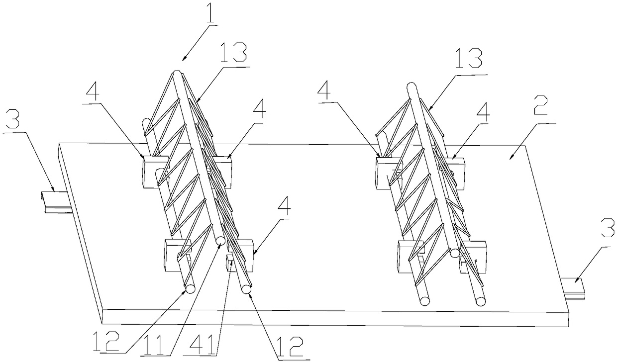
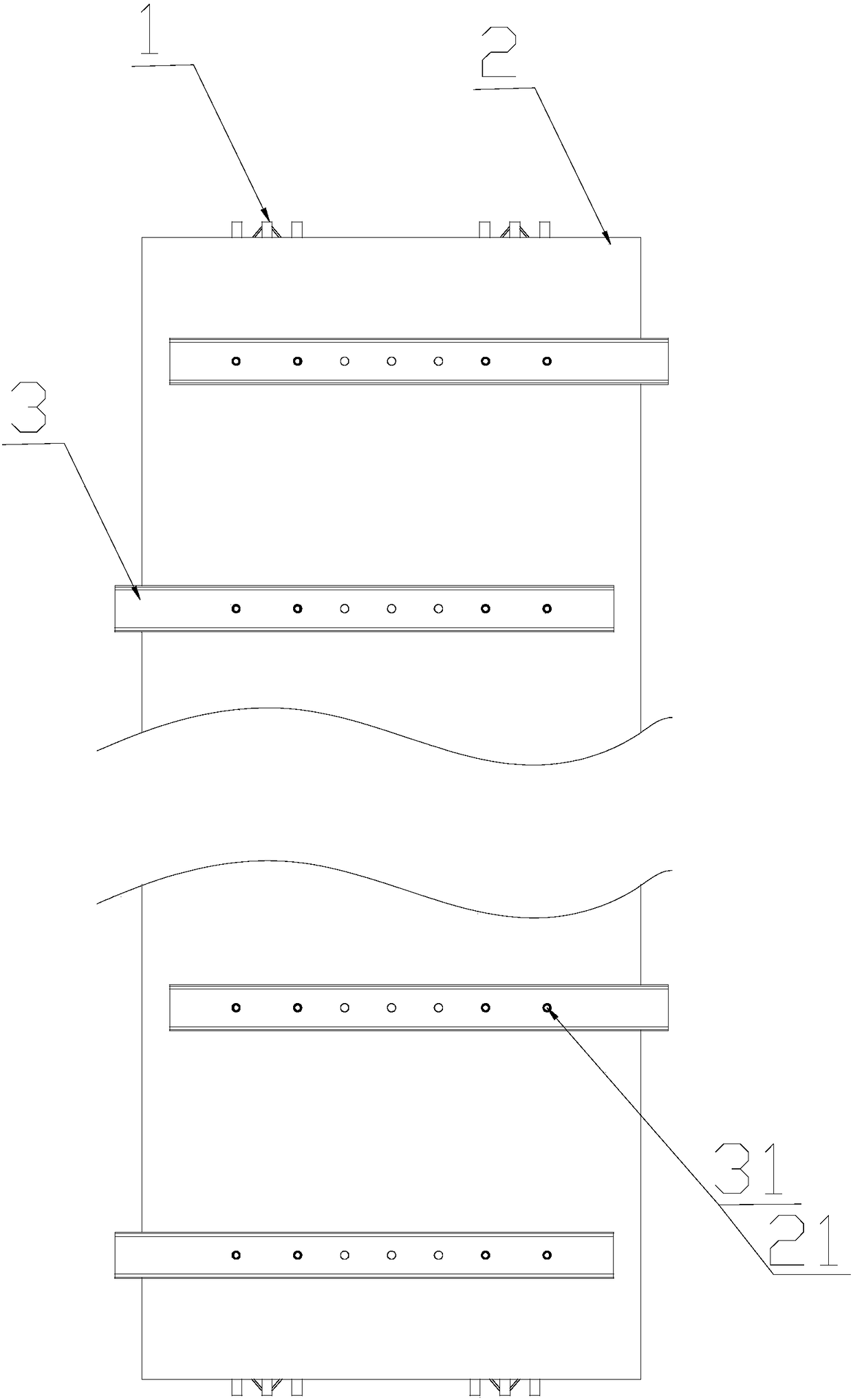
[0029] like Figure 1-3 As shown, a prefabricated steel truss floor deck comprises a steel truss 1 , a connecting piece 4 , a floor deck 2 and a supporting piece 3 . The steel bar truss 1 includes an upper chord steel bar 11 and two lower chord steel bars 12 , and the two lower chord steel bars 12 are respectively welded and connected to the upper chord steel bar 11 through the web bar steel bar 13 . The two lower chord reinforcing bars 12 are connected with connecting pieces 4 relative to each other. The connecting piece 4 includes a slot 41 penetrating the connecting piece 4 with a side opening, and the lower end of the connecting piece 4 is provided with a threaded hole. The connecting pieces 4 are clamped on the two lower chord steel bars 12 in pairs, and each pair of connecting pieces 4 is longitudinally arranged on the steel bar truss 1 . The floor deck 2 is connected with a support member 3 on the side away from the steel truss 1, and the support members 3 are distrib...

Embodiment 2

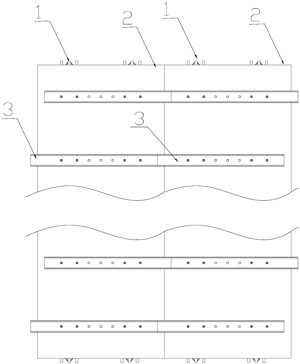
[0033] like Figure 4 As shown, the difference between this embodiment and the first embodiment is that every two supporting members 3 alternately protrude from the left and right sides of the floor deck 2. Of course, the supporting members 3 can also be staggered and protruding from the floor deck every two. 2 left and right sides.

Embodiment 3

[0035] like Figure 5 As shown, the difference between this embodiment and the first embodiment is that the length of the support member 3 is greater than the width of the floor deck 2 , and the two ends of the support member 3 protrude from the left and right sides of the floor deck 2 . Therefore, the supports 3 of the adjacent prefabricated steel truss floor decks are dislocated and distributed. When splicing, both ends of the supports 3 support the adjacent floor decks 2 to reduce the dislocation of the splicing joints. Of course, if Image 6As shown, when the floor deck 3 is wider, the middle part of the support member 3 can also be disconnected to form a pair of first support parts 32 and second support parts extending from the left and right ends of the floor deck 2 33.


PUM


Abstract

The invention relates to the technical field of building materials, in particular to an assembled steel bar truss floor support plate which comprises a floor support plate body. One side of the floorsupport plate body is detachably connected with a steel bar truss, and supporting parts are arranged on the other side of the floor support plate body at intervals and extend out of the floor supportplate body. According to the floor support plate, the supporting parts are arranged on the lower side of the floor support plate and extend out of the left or the right of the floor support plate, extending portions of the supporting parts support adjacent floor support plates when the floor support plates are spliced, the floor support plates of two sides of a splicing seam are supported by the supporting parts, misplacement of the splicing seam is decreased and even disappeared, the supporting parts are disassembled when the floor support plate is disassembled, extra supporting part disassembling workload is not increased, and the reusable floor support plate and the reusable supporting parts are more stably and efficiently used.

Description

technical field [0001] The invention relates to the technical field of building materials, in particular to an assembled steel truss floor deck. Background technique [0002] In general floor pouring, the steel trusses and floor decks produced in the factory are detachably assembled, and the floor decks equipped with the steel trusses are spliced ​​at the construction site, and concrete is poured. After the concrete solidifies, the floor decks are dismantled and reused. In this way, it can be produced in factories, reducing the impact of the environment and weather on the construction period, and the truss production is safe and quality is guaranteed. However, when the existing floor slabs are spliced ​​at the construction site, splicing joints are left. When pouring concrete, due to the weight of the concrete, the splicing joints of the floor slabs are dislocated, making the poured floor uneven. [0003] In order to solve the above problems, the seam fixing plate is usuall...

Claims


Application Information

Patent Timeline
IPC IPC(8): E04B5/38
CPCE04B5/38E04B5/29E04C5/065
Inventor 陈永德
Owner ZHE JIANG ZHONGYI BUILDING MATERIALS TECH CO LTD
Why Eureka
Try Eureka