
Distinguishing and positioning of mirror traffic

A technology of traffic analysis and mirroring, applied in data exchange through path configuration, digital transmission system, electrical components, etc., can solve the problems of large increase in the number of data acquisition cards, increase in hardware costs, and lack of positioning, etc., to reduce data Collect interfaces, accurately distinguish and locate, and achieve low-cost effects

Inactive Publication Date: 2018-05-29
CHINA UNIONPAY
View PDF6 Cites 1 Cited by
  • Summary
  • Abstract
  • Description
  • Claims
  • Application Information

AI Technical Summary

Problems solved by technology

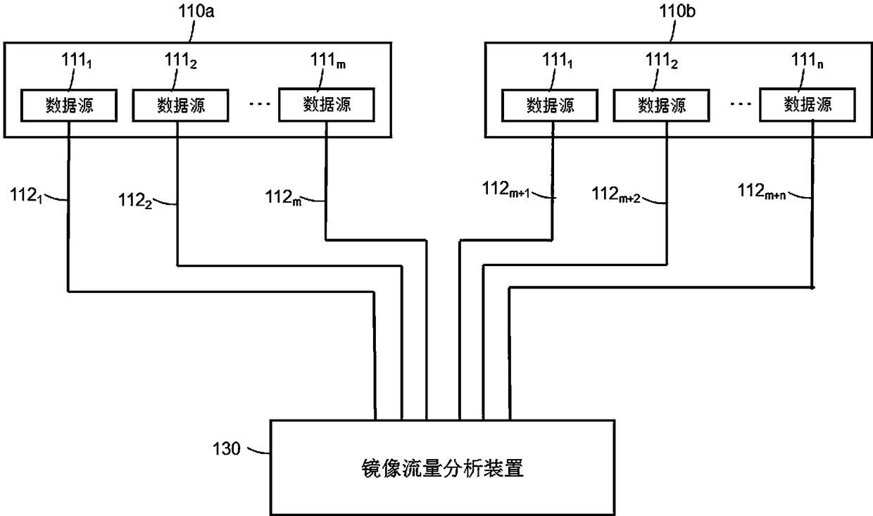
[0004] However, as the production network deploys more and more network traffic mirroring points, the number of data sources becomes larger and larger, and the number of mirrored traffic becomes larger; therefore, relying on the data collection interface of the mirrored traffic analysis device 13 The linear increase to meet the significant increase in the number of mirrored traffic, like this, the data acquisition interface of the mirrored traffic analysis device 13 corresponds to a large increase in the number of data acquisition cards, and the hardware cost increases greatly; or, due to the data acquisition interface of the mirrored traffic analysis device 13 The number is limited, and more mirrored traffic analysis devices 13 need to be set up to analyze more data sources
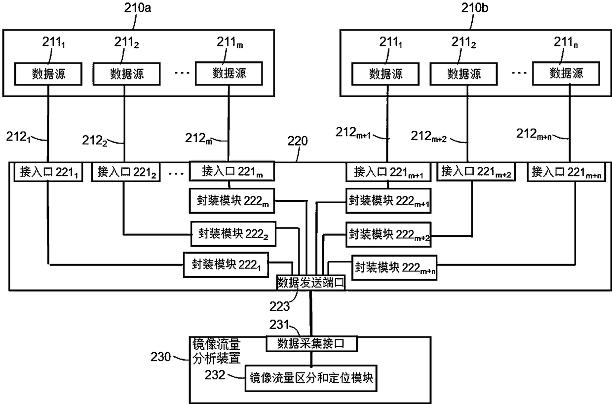
[0005] And, in the case of figure 1 In the network flow monitoring system shown, since different services may not change the original IP address before and after passing through different devices, if these flows are processed through a data collection interface, it is difficult to mirror the flow 112 on the flow mirror flow analysis device 230 distinguish them, let alone locate them
In this way, it becomes very inconvenient to troubleshoot production network faults and manage network traffic.

Method used


Image

  • Distinguishing and positioning of mirror traffic
  • Distinguishing and positioning of mirror traffic
  • Distinguishing and positioning of mirror traffic

Examples


Embodiment Construction

[0043] The following introduces some of the possible embodiments of the present invention, which are intended to provide a basic understanding of the present invention, but are not intended to identify key or decisive elements of the present invention or limit the scope of protection. It is easy to understand that, according to the technical solution of the present invention, those skilled in the art may propose other alternative implementation manners without changing the essence and spirit of the present invention. Therefore, the following specific embodiments and drawings are only exemplary descriptions of the technical solution of the present invention, and should not be regarded as the entirety of the present invention or as a limitation or restriction on the technical solution of the present invention.

[0044] Some of the block diagrams shown in the drawings are functional entities and do not necessarily correspond to physically or logically separate entities. These fun...


PUM


Abstract

The invention relates to distinguishing and positioning of mirror traffic, and belongs to the technical field of network traffic mirroring. A network mirror traffic monitoring system provided by the invention comprises a traffic convergence switch and a mirror traffic analysis device, wherein the traffic convergence switch is configured to perform message packaging on mirror traffic data receivedvia a corresponding access of the traffic convergence switch based on a QinQ technology to form the mirror traffic data with a second message format in which at least one VLAN label is added with respect to a first message format, the VLAN label comprises the identification information corresponding to the access for receiving the mirror traffic data with the first message format. A mirror trafficanalysis device distinguishes and positions the mirror traffic data according to the VLAN label in the mirror traffic data with the second message format.

Description

technical field [0001] The invention belongs to the technical field of network traffic mirroring, and relates to the distinction and positioning of mirrored traffic. Background technique [0002] Mirroring is the process of duplicating monitored traffic and forwarding the duplicated traffic (also referred to as "mirrored traffic") to a monitoring device including, for example, mirrored traffic analysis means. The port of the monitored traffic is the mirroring source port, and the monitoring device runs corresponding traffic monitoring software to monitor the network traffic of each mirroring source port, for example, in real time and visualized. Therefore, mirroring technology is currently a conventional technology for monitoring network traffic. [0003] figure 1 Shown is a schematic structural diagram of a network traffic monitoring system in the prior art. Wherein, the mirror traffic analysis device 130 is used to monitor the network traffic of multiple different produ...

Claims


Application Information

Patent Timeline
IPC IPC(8): H04L12/26H04L12/931H04L29/08H04L12/46
CPCH04L12/4633H04L12/465H04L43/0876H04L49/208H04L67/1095
Inventor 陈华俊李莉莎季陆军牛子孺
Owner CHINA UNIONPAY
Learn More