Novel electromechanical device heat dissipation box

A technology for electromechanical equipment and heat dissipation box, which is applied to the structural parts of electrical equipment, electrical components, cooling/ventilation/heating renovation, etc. problem, to achieve the effect of increasing the area, speeding up the heat dissipation effect, and strengthening the heat dissipation effect

Inactive Publication Date: 2018-05-29
HENAN YUNLE TECH CO LTD
View PDF0 Cites 1 Cited by
  • Summary
  • Abstract
  • Description
  • Claims
  • Application Information

AI Technical Summary

Problems solved by technology

[0007] In order to solve the problems of poor heat dissipation effect, high heat dissipation effect on the surrounding environment and high energy consumption required for heat dissipation when the existing electromechanical equipment uses air cooling for heat dissipation, the invention provides a new type of electromechanical equipment cooling box

Method used


Image

  • Novel electromechanical device heat dissipation box
  • Novel electromechanical device heat dissipation box
  • Novel electromechanical device heat dissipation box

Examples


Embodiment 1

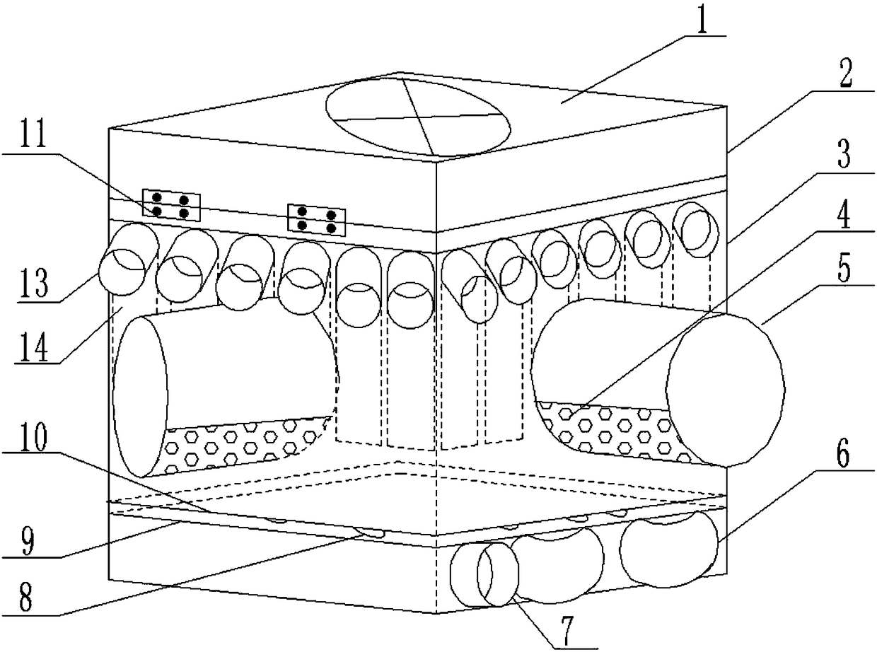
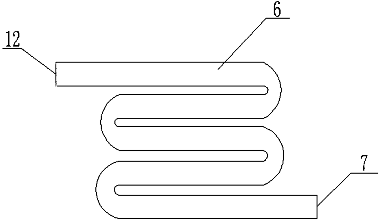
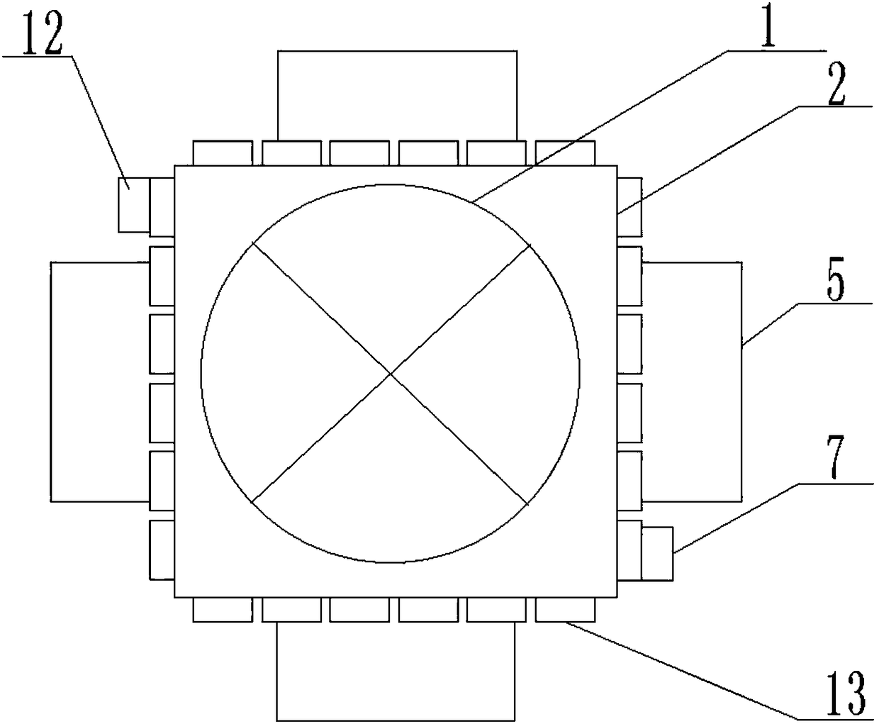
[0043] Such as Figure 1-8 As shown, a new type of cooling box for electromechanical equipment includes a box body 3, the top of the box body 3 is provided with a box cover 2, and the box cover 2 is embedded with an exhaust fan 1, and the box cover 2 and the box body 3 are flexibly connected, the upper edge of the side wall of the box body 3 is provided with an air guide tube 16, and the air guide tube 16 includes a first ventilation tube 13 and a second ventilation tube 14, and the first ventilation tube 13 is horizontally arranged on the box body 3, the second ventilation pipe 14 is arranged inside the box body 3 along the vertical direction, and the other end of the second ventilation pipe 14 is 3-5 cm above the water cooling plate 9, and the first ventilation pipe 13 communicates with the second ventilation pipe 14; the four side walls of the box body 3 are respectively provided with the wire-passing pipeline 5, and the lower part of the pipe wall of the wire-passing pipel...

Embodiment 2

[0045] Such as Figure 1-8 As shown, a new type of cooling box for electromechanical equipment includes a box body 3, the top of the box body 3 is provided with a box cover 2, and the box cover 2 is embedded with an exhaust fan 1, and the box cover 2 and the box body 3 are flexibly connected, the upper edge of the side wall of the box body 3 is provided with an air guide tube 16, and the air guide tube 16 includes a first ventilation tube 13 and a second ventilation tube 14, and the first ventilation tube 13 is horizontally arranged on the box body 3, the first vent pipe 13 is provided with a filter screen 15; the second vent pipe 14 is arranged inside the box body 3 along the vertical direction, and the first vent pipe 13 and the second vent pipe Trachea 14 is communicated; The four side walls of described box body 3 are provided with described wire-passing pipeline 5 respectively, and the bottom of the pipe wall of described wire-passing pipeline 5 is provided with some thro...

Embodiment 3

[0047] Such as Figure 1-8 As shown, a new type of cooling box for electromechanical equipment includes a box body 3, the top of the box body 3 is provided with a box cover 2, and the box cover 2 is embedded with an exhaust fan 1, and the box cover 2 and the box body 3 are flexibly connected, the upper edge of the side wall of the box body 3 is provided with an air guide tube 16, and the air guide tube 16 includes a first ventilation tube 13 and a second ventilation tube 14, and the first ventilation tube 13 is horizontally arranged on the box body 3, a filter screen 15 is provided inside the first ventilation pipe 13; the second ventilation pipe 14 is arranged inside the box body 3 along the vertical direction, and the other end of the second ventilation pipe 14 is at a distance from 3-5cm above the water cooling plate 9, the first ventilation pipe 13 and the second ventilation pipe 14 are in communication; The lower part of the pipe wall is provided with several through hol...


PUM


Abstract

The invention belongs to the electromechanical device technology field and discloses a novel electromechanical device heat dissipation box. By using existing electromechanical device, when air coolingis used to carry out heat dissipation, a heat dissipation effect is poor, the requirement of the heat dissipation effect to a surrounding environment is high and energy consumption required by the heat dissipation is high. By using the heat dissipation box of the invention, the above problems are solved. The heat dissipation box comprises a box body. The top end of the box body is provided witha box cover. An exhaust fan is embedded in the box cover. The box cover and the box body are movably connected. The upper edge of the side wall of the box body is provided with an air-guide pipe. Theair-guide pipe comprises a first breather pipe and a second breather pipe. The first breather pipe is horizontally arranged on the side wall of the box body. The second breather pipe is arranged in the box body along a vertical direction. The first breather pipe and the second breather pipe are connected. The four side walls of the box body are provided with line-passing pipelines. The lower portion of the pipe wall of each line-passing pipeline is provided with several through holes. The bottom of the box body is provided with a water-cooling component. The water-cooling component comprises awater cooling plate and a water cooling pipeline. The water cooling pipeline comprises a water inlet and a water outlet which are connected to each other. The water cooling plate is arranged above the water cooling pipeline.

Description

technical field [0001] The invention relates to the field of electromechanical equipment, in particular to a novel cooling box for electromechanical equipment. Background technique [0002] With the continuous improvement of people's living standards, people's demand for electromechanical equipment in daily life is increasing. From transportation to various household appliances, computers, printers, etc., electromechanical products have become indispensable in people's life. Advanced mechanical and electrical equipment can greatly increase labor productivity, reduce labor intensity, improve the production environment, and complete tasks that cannot be completed by manpower. It has a direct and important impact on the development of the entire national economy, as well as the improvement of science and technology and national defense strength. Most electromechanical equipment converts electrical energy into mechanical energy, so a lot of heat will be generated during operatio...

Claims


Application Information

Patent Timeline
Patent Type & Authority Applications(China)
IPC IPC(8): H05K7/20
CPCH05K7/20136H05K7/20181H05K7/20272
Inventor 肖海波
Owner HENAN YUNLE TECH CO LTD
Why Eureka
Try Eureka