
Crushing and grinding device for discarded brick

A technology of discarded bricks and grinding powder, applied in grain processing, etc., can solve the problems of affecting the appearance of the city, occupying land, and labor intensity of workers

Inactive Publication Date: 2018-06-01
张耀祥
View PDF0 Cites 6 Cited by
  • Summary
  • Abstract
  • Description
  • Claims
  • Application Information

AI Technical Summary

Problems solved by technology

[0002] A lot of construction waste will be generated in the process of building and demolishing houses, most of which are damaged bricks. Since they cannot be used again, most of the bricks are discarded or simply landfilled. This practice not only wastes a lot resources, but also occupy land and affect the appearance of the city
[0003] In construction sites, a lot of crushed stone materials are often needed as the foundation of the ground. After the bricks are broken into pieces, they can supplement the crushed stone materials very well. When the crushed stone materials are sufficient, the powder after manual grinding of the bricks is the permeable brick. One of the raw materials for making bricks, the efficiency of manually breaking bricks or grinding powder is relatively low, and long-term work also brings greater labor intensity to workers; in the prior art, there is no method that can take out broken bricks and brick powder respectively. device, and sometimes broken bricks are needed on the construction site and sometimes brick powder is needed. A single function cannot meet the needs of different situations on the construction site.

Method used


Image

  • Crushing and grinding device for discarded brick
  • Crushing and grinding device for discarded brick
  • Crushing and grinding device for discarded brick

Examples


Embodiment Construction

[0026] Below in conjunction with accompanying drawing and embodiment of description, specific embodiment of the present invention is described in further detail:

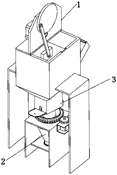
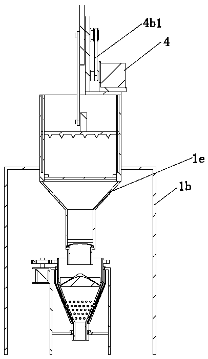
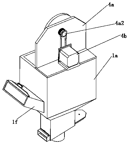
[0027] refer to Figure 1 to Figure 8 The shown crushing and grinding device for waste bricks includes a crushing mechanism 1, a grinding mechanism 2 and a material distribution mechanism 3, the crushing mechanism 1 is located directly above the grinding mechanism 2, and the material distribution mechanism 3 is located Between the mechanism 1 and the milling mechanism 2, the crushing mechanism 1 includes a storage cabinet 1a, a crushing assembly and a drive assembly 4 for driving the crushing assembly to move in the vertical direction, and both sides of the storage cabinet 1a are provided with There is an L-shaped support plate 1b for supporting the storage cabinet 1a, the crushing assembly is located in the storage cabinet 1a, the drive assembly 4 is located directly above the crushing assembly, and the grinding me...


PUM


Abstract

The invention relates to the field of brick crushing device, in particular to a crushing and grinding device for a discarded brick. The crushing and grinding device for the discarded brick comprises acrushing mechanism, a grinding mechanism and a distributing mechanism. The broken mechanism is arranged just above the grinding mechanism. The distributing mechanism is arranged between the crushingmechanism and the grinding mechanism. The crushing mechanism includes a storage cabinet, a crushing assembly and a driving assembly. L-shaped supporting plates are arranged on both sides of the storage cabinet. The grinding mechanism includes a rotary barrel and a bearing plate. The rotary barrel is arranged in a vertical mode, and the rotary barrel is of an inverted-cone structure. A broken brickinlet is formed in the top portion of the rotary barrel. A first bearing is arranged between the rotary barrel and the bearing plate. Two side plates are arranged at the bottom portion of the bearingplate. According to the crushing and grinding device for the discarded brick, the crushing and grinding towards a workpiece are carried out by the crushing and grinding device, the labor strength ofa worker is reduced; the broken brick can be taken out by the distributing mechanism when the broken brick is needed, and brick powder can be taken out when the brick powder is needed, so that the needs of different conditions on the site are met.

Description

technical field [0001] The invention relates to the field of brick crushing devices, in particular to a crushing and grinding device for waste bricks. Background technique [0002] A lot of construction waste will be generated in the process of building and demolishing houses, most of which are damaged bricks. Since they cannot be used again, most of the bricks are discarded or simply landfilled. This practice not only wastes a lot resources, but also occupy land and affect the appearance of the city. [0003] In construction sites, a lot of crushed stone materials are often needed as the foundation of the ground. After the bricks are broken into pieces, they can supplement the crushed stone materials very well. When the crushed stone materials are sufficient, the powder after manual grinding of the bricks is the permeable brick. One of the raw materials for making bricks, the efficiency of manually breaking bricks or grinding powder is relatively low, and long-term work al...

Claims


Application Information

Patent Timeline
IPC IPC(8): B02C18/02B02C18/04B02C19/00B02C23/16
CPCB02C18/02B02C18/0084B02C18/04B02C19/00B02C23/16B02C2023/165
Inventor 张耀祥
Owner 张耀祥
Learn More