Main shaft annular water spraying device

A water spray device and ring-shaped technology, which is applied in the field of machining spindle, tool cooling, and machining machine tool spindle, can solve the problems of low efficiency in the debugging stage, uneven tool cooling, cumbersome manual adjustment, etc., and achieve convenient and accurate automatic adjustment , Improve the degree of automation and processing efficiency, and avoid damage

Pending Publication Date: 2018-06-01
鲁光波
View PDF0 Cites 1 Cited by
  • Summary
  • Abstract
  • Description
  • Claims
  • Application Information

AI Technical Summary

Problems solved by technology

[0010] The purpose of the present invention is to: propose a spindle annular water spray device, after solving the change of the length of the tool in the actual mechanical processing, it is necessary to manually adjust the joint water pipes and nozzles one by one, and adjust the nozzles. Problems such as low stage efficiency and uneven tool cooling

Method used


Image

  • Main shaft annular water spraying device
  • Main shaft annular water spraying device
  • Main shaft annular water spraying device

Examples


Embodiment Construction

[0043] The following non-limiting examples illustrate the invention.

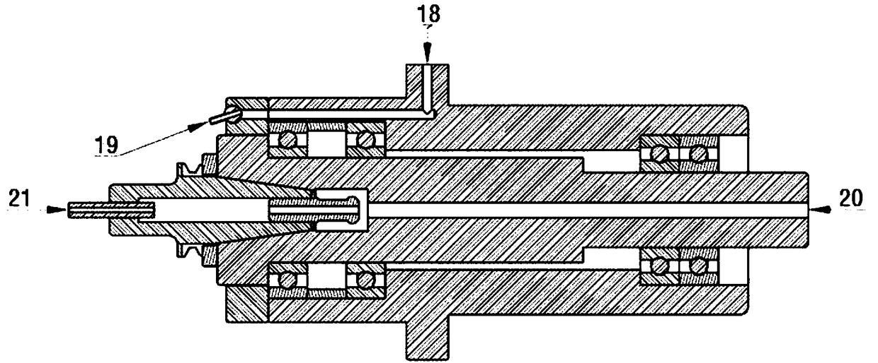
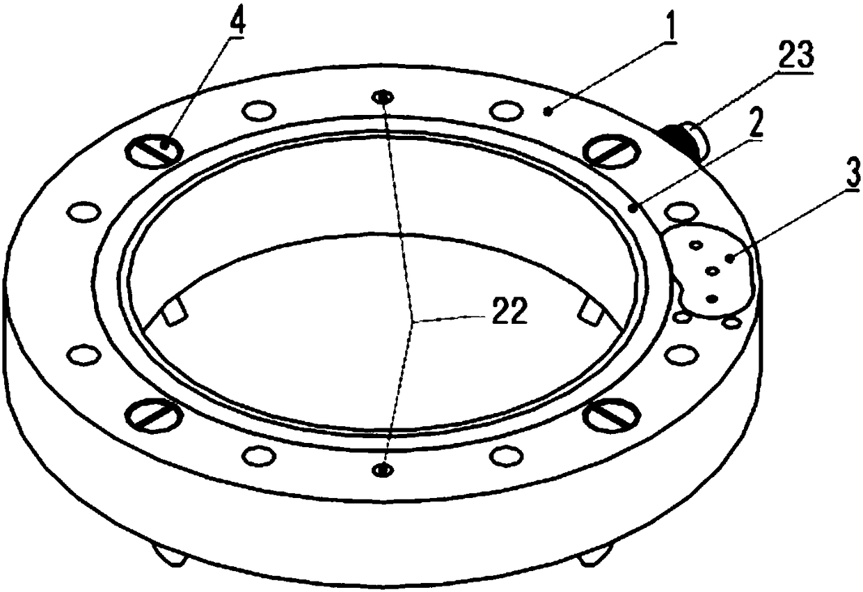
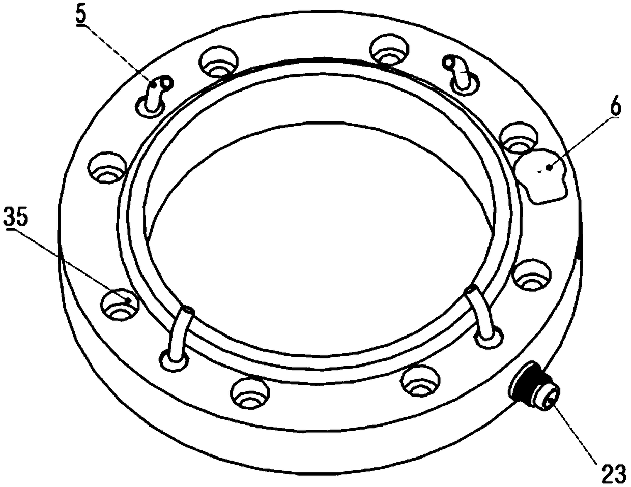
[0044] refer to Figure 1-17 as shown, figure 2 , 3 It mainly embodies the overall structure of the appearance of the present invention; Figure 4-6 It mainly reflects the structure of the overall internal waterway, the gear box installation groove 24, the nozzle group installation hole 27, the position of the cutting fluid inlet, and the limit card groove structure; Figure 7-9 It embodies the cooperative structural relationship between each part of the water spray device and the main body 1 of the annular end cover; Figure 10 It further embodies the distribution and shape of the internal water tank 28, the communication mode with each water spray device, and the transmission mode and installation position of the ring gear 7 and the gear set 13; Figure 11 It embodies the transmission relationship and transmission principle of all components from the drive motor 12 to the final nozzle 5; Figure 12 ...


PUM


Abstract

The invention discloses a main shaft annular water spraying device, and belongs to the field of machining machine tool main shafts. The main shaft annular water spraying device comprises an annular end cover main body, a gear ring and water spraying devices; the gear ring cooperates with the annular end cover main body, and can be coaxially rotated relative to the annular end cover main body; an internal water tank is formed in the annular end cover main body; the annular end cover main body is provided with a water inlet communicating with the internal water tank; the annular end cover main body is provided with multiple water spraying devices along the internal water tank; the water spraying devices are provided with nozzles; the nozzles communicate with the internal water tank through the water spraying devices; and when each water spraying device is coaxially rotated along with the gear ring relative to the annular end cover main body, each water spraying device synchronously and consistently swings back and forth in the axial direction relative to the gear ring. The main shaft annular water spraying device is compact in structure and free of occupying external space near mainshafts, can totally save external water spraying pipes, can automatically adjust the positions of the nozzles to achieve higher convenience and accuracy, improves the cutter cutting conditions, reduces the defect of gradual manual adjustment, and improves the automation degree and the machining efficiency of machine tools.

Description

technical field [0001] The invention belongs to the field of mechanical processing machine tool spindles, in particular to the field of mechanical processing spindles and tool cooling, and is used for the supporting parts of mechanical processing machine tools. Background technique [0002] In the CNC milling machine, CNC machining center, and CNC drilling and tapping center in the machining industry, there are three main structural forms of spindle cooling and tool cooling: [0003] 1. If Figure 17 , by spraying cooling water through the bone-saving water pipe 15 near the main shaft, or blowing cooling air through the trachea. [0004] 2. If figure 1 , the cooling liquid is sprayed from the nozzle water outlet 19 near the main shaft through the nozzle water inlet hole 18 through the inside of the main shaft. [0005] 3. If figure 1 , the coolant passes through the main shaft water inlet hole 20 to the tool handle through the center of the main shaft, and then sprays o...

Claims


Application Information

Patent Timeline
Patent Type & Authority Applications(China)
IPC IPC(8): B05B3/14
CPCB05B3/14
Inventor 鲁光波
Owner 鲁光波
Why Eureka
Try Eureka