Laser head fixing device of laser cutting machine

A technology of laser cutting machine and fixing device, which is applied to laser welding equipment, welding equipment, metal processing equipment and other directions, can solve the problems of increasing labor intensity of operators, difficult disassembly, complicated fixing structure, etc. Good fixing effect and easy to use effect

Inactive Publication Date: 2018-06-01
王虎林
View PDF0 Cites 4 Cited by
  • Summary
  • Abstract
  • Description
  • Claims
  • Application Information

AI Technical Summary

Problems solved by technology

[0003] In the prior art, the laser head fixing device of the existing laser cutting machine has a complex fixing structure, and it is difficult to disassemble, which increases the labor intensity of the operators. In the prior art, the laser head of the exis

Method used


Image

  • Laser head fixing device of laser cutting machine
  • Laser head fixing device of laser cutting machine
  • Laser head fixing device of laser cutting machine

Examples


Example Embodiment

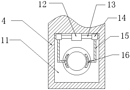
[0024] Specific embodiments: The operator first holds the laser head 5, puts the upper end of the laser head 5 in the through hole, keeps it still, and then runs the bidirectional motor 12, the bidirectional motor 12 drives the screw 13 to rotate, and the screw 13 rotates to drive the nut seat 14 moves to the left, the nut base 14 drives the L-shaped support rod 15 to move to the left, and the L-shaped support rod 15 drives the fixed plate 16 to move to the left. When the fixed plate 16 is attached to the laser head 5, the bidirectional motor 12 continues to rotate, and then Make the fixing plate 16 continue to move to the left to fix the laser head 5. When it is necessary to disassemble, the operator runs the bidirectional motor 12, the bidirectional motor 12 drives the screw 13 to rotate, and the screw 13 rotates to drive the nut base 14 to move to the right. The nut seat 14 drives the L-shaped support rod 15 to move to the right, and the L-shaped support rod 15 drives the fix...


PUM


Abstract

The invention provides a laser head fixing device of a laser cutting machine. The laser head fixing device comprises an installation groove, a two-way motor, a nut seat, a rotary shaft, a supporting rod, a groove, an electric push rod, a cleaning brush and a protective plate. The installation groove is formed in the upper end face of a rack, the two-way motor is fixed to the rear portion of the lower end face of the interior of the installation groove, and the nut seat is installed on the annular side face of a lead screw through a ball nut pair; and according to the design, the functions thatthe fixing effect is good, and disassembly is convenient are achieved. The rotary shaft is installed on the right portion of the upper end face of the interior of the groove through a boss, the supporting rod is connected with the groove through the rotary shaft, and the electric push rod is fixed to the upper end face of the interior of the protective plate; the cleaning brush is connected withthe electric push rod through a connecting rod, the cleaning brush is assembled to the front end of the annular side face of the laser head, and the protective plate is fixed to the lower end of the supporting rod; and according to the design, the functions that the laser head is protected, and cleaning is convenient are achieved. According to the laser head fixing device, using is convenient, thefixing effect is good, disassembly is convenient, the laser head is protected, cleaning is convenient, and the reliability is high.

Description

Technical field [0001] The invention is a laser head fixing device of a laser cutting machine, belonging to the field of laser cutting machine equipment. Background technique [0002] The laser cutting machine focuses the laser light emitted from the laser into a high-power density laser beam through the optical path system. The laser beam irradiates the surface of the workpiece to make the workpiece reach the melting point or boiling point. At the same time, the high-pressure gas coaxial with the beam blows away the molten or vaporized metal. As the beam moves relative to the workpiece, the material will eventually form a slit to achieve The purpose of cutting. [0003] In the prior art, the fixing structure of the laser head fixing device of the existing laser cutting machine is complicated, and it is difficult to disassemble, which increases the labor intensity of the operator. In the prior art, the laser head of the existing laser cutting machine has no protective mechanism W...

Claims


Application Information

Patent Timeline
IPC IPC(8): B23K26/38B23K26/70
CPCB23K26/38B23K26/702
Inventor 王虎林
Owner 王虎林
Why Eureka
Try Eureka