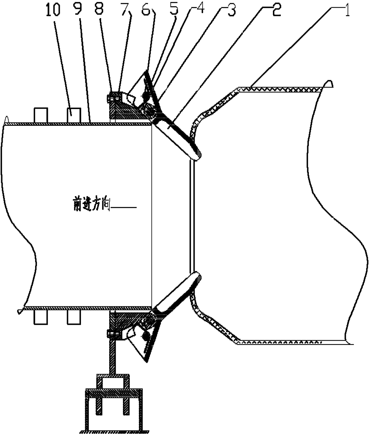
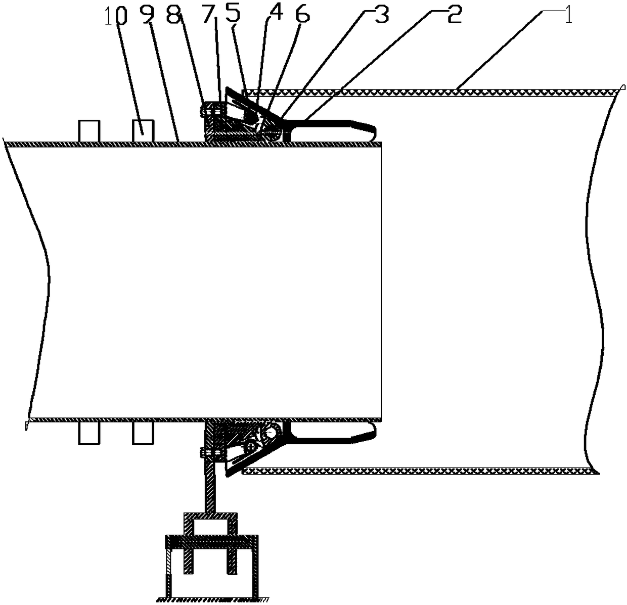
Rubber pipe port expanding device for heat insulation pipe

A technology for rubber tubes and thermal insulation tubes, applied in the field of thermal insulation tube manufacturing devices, can solve problems such as high risk, difficult operation, time-consuming and laborious, etc., and achieve the effect of increasing the processing range, processing speed and processing safety

Pending Publication Date: 2018-06-01
天津市九赢百信科技有限公司
View PDF0 Cites 2 Cited by
  • Summary
  • Abstract
  • Description
  • Claims
  • Application Information

AI Technical Summary

Problems solved by technology

[0002] In the current pipeline industry, in the production process of the insulation pipe, the steel pipe penetrates the deformed rubber tube and regularly places the support blocks on the iron pipe. There are two operation methods: method 1. The deformed rubber tube is placed On the rack, the steel pipe that needs to be penetrated is placed on the automatic forward transmission rack that is in a straight line with the rubber pipe rack. The deformed rubber pipe mouths are lifted one by one, so that the iron pipe with the support block can enter the rubber pipe, so that each set of support blocks must be manually lifted one by one when entering the deformed rubber pipe mouth, which is time-consuming and laborious; A guide head is buckled on the head to guide the head of the steel pipe into the deformed rubber tube, but when the support block at the back enters the deformed rubber tube, it still cannot enter the deformed rubber tube smoothly, and the deformed rubber tube needs to be manually Lift up one by one to allow each group of support blocks to enter; the existing two methods of manual operation are time-consuming and labor-intensive. In the case of a large rubber tube diameter, the operation is very dangerous due to the high diameter of the rubber tube; especially in the rubber tube Difficult to handle with thick walls

Method used


Image

  • Rubber pipe port expanding device for heat insulation pipe
  • Rubber pipe port expanding device for heat insulation pipe

Examples


Embodiment Construction

[0017] It should be noted that, in the case of no conflict, the embodiments of the present invention and the features in the embodiments can be combined with each other.

[0018] In describing the present invention, it should be understood that the terms "center", "longitudinal", "transverse", "upper", "lower", "front", "rear", "left", "right", " The orientations or positional relationships indicated by "vertical", "horizontal", "top", "bottom", "inner" and "outer" are based on the orientations or positional relationships shown in the drawings, and are only for the convenience of describing the present invention and Simplified descriptions, rather than indicating or implying that the device or element referred to must have a particular orientation, be constructed and operate in a particular orientation, and thus should not be construed as limiting the invention. In addition, the terms "first", "second", etc. are used for descriptive purposes only, and should not be understood ...


PUM


Abstract

The invention provides a rubber pipe port expanding device for a heat insulation pipe. The device comprises supporting mechanisms and a supporting arm mounting rack, wherein a plurality of supportingmechanisms encircle a circular structure and are uniformly distributed on the supporting arm mounting rack; each supporting mechanism comprises a supporting arm and a supporting arm base; the supporting arms are arranged on the supporting arm bases through rotating hinging shafts; a supporting spring is clamped between each supporting arm and the corresponding supporting arm base and is used for expanding each supporting arm and the corresponding supporting arm base, and thus the plurality of supporting arms can be kept in one angle in order to encircle a cone structure; the minimum diameter of a cone angle of the cone structure is less than the rubber pipe port deformation range. According to the device, the operation is completely mechanically carried out, so that the problem of manual threading of an existing heat insulation pipe in processing can be solved; the whole processing of the heat insulation pipe is completely automatically performed, so that the processing speed and the processing safety are greatly improved; and moreover, the heat insulation pipe processing range is greatly expanded; rubber pipes with thicker walls can be processed; and heat insulation pipe which higher diameter can be processed.

Description

technical field [0001] The invention belongs to the technical field of heat preservation pipe manufacturing devices, and in particular relates to a rubber pipe opening device for heat preservation pipes. Background technique [0002] In the current pipeline industry, in the production process of the insulation pipe, the steel pipe penetrates the deformed rubber tube and regularly places the support blocks on the iron pipe. There are two operation methods: method 1. The deformed rubber tube is placed On the rack, the steel pipe that needs to be penetrated is placed on the automatic forward transmission rack that is in a straight line with the rubber pipe rack. The deformed rubber pipe mouths are lifted one by one, so that the iron pipe with the support block can enter the rubber pipe, so that each set of support blocks must be manually lifted one by one when entering the deformed rubber pipe mouth, which is time-consuming and laborious; A guide head is buckled on the head to...

Claims


Application Information

Patent Timeline
Patent Type & Authority Applications(China)
IPC IPC(8): B29C63/18
CPCB29C63/18
Inventor 李刚
Owner 天津市九赢百信科技有限公司
Why Eureka
Try Eureka