Fast mud dehydrating device

A rapid dehydration and slurry technology, applied in water/sludge/sewage treatment, dehydration/drying/concentrated sludge treatment, sludge treatment, etc., can solve the problem of blocked vacuum transmission, inconspicuous treatment effect, and reduced treatment efficiency, etc. problem, to achieve the effect of uniform vacuum pressure distribution, guaranteed reinforcement effect, and fast reinforcement speed

Inactive Publication Date: 2018-06-01
WUHAN UNIV
View PDF7 Cites 13 Cited by
  • Summary
  • Abstract
  • Description
  • Claims
  • Application Information

AI Technical Summary

Problems solved by technology

Under the action of this pressure difference, the pore water in the soil is continuously discharged from the drainage channels, thereby consolidating the soil. However, the engineering practice shows that due to problems such as silting of plastic drainage boards and obstruction of vacuum transmission after soil reinforcement, etc. Problems such as the post-processing efficiency reduction of vacuum preloading method, and the processing effect is not obvious, etc.

Method used


Image

  • Fast mud dehydrating device
  • Fast mud dehydrating device
  • Fast mud dehydrating device

Examples


Embodiment 1

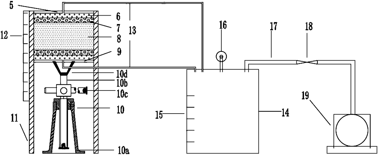
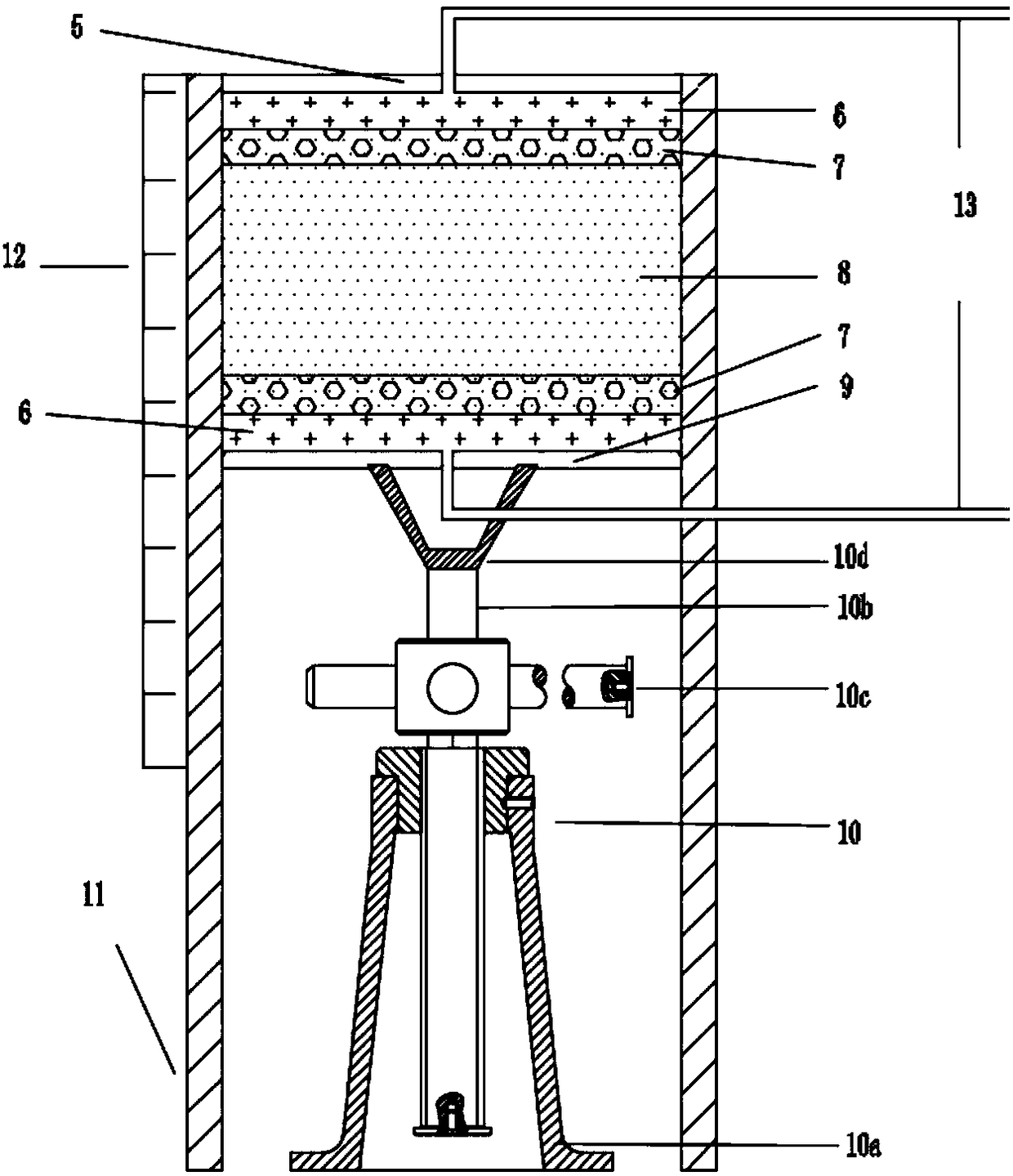
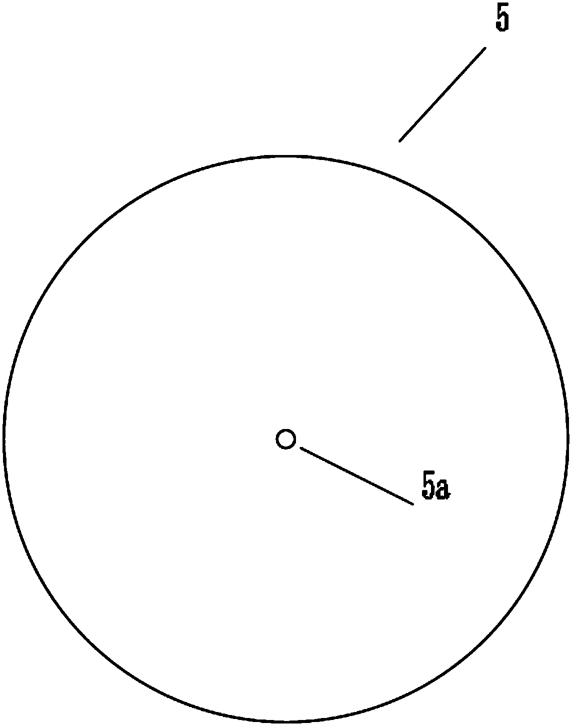
[0029] A quick mud dewatering device, mainly comprising a mud dewatering box, a hydraulic jack 10 and a two-way vacuum filtration system; the mud dewatering box includes a cylindrical box 11, and the cylindrical box 11 is sequentially provided with a top plate 5, a geotechnical Fabric layer 6, sand cushion layer 7, mud layer 8, sand cushion layer 7, geotextile layer 6 and bottom plate 9; Described top plate 5, bottom plate 9, geotextile layer 6, sand cushion layer 7 diameters and cylindrical box 11 The inner diameters are matched; the side of the top plate 5 is provided with external threads, and the top of the cylindrical box 11 is provided with internal threads corresponding to the top plate 5; the top plate 5 is provided with a vacuum filtration channel 5a, and the bottom plate 9 is provided with a vacuum filtration channel 9a; Both the top plate 5 and the bottom plate 9 are made of impermeable material.

[0030] The top of the screw rod of the hydraulic jack 10 is welded w...

Embodiment 2

[0034] A quick mud dehydration device, on the basis of the structure of Embodiment 1, is equipped with a material system for injecting mud into the mud layer 8 of the mud dewatering box; the material system includes a mud mixing tank 1 and a pump 4 connected in sequence A valve 2 is arranged on the communication pipeline between the mud mixing barrel 1 and the pump 4, and the transportation pipe 3, and the transportation pipe 3 is connected to the mud layer 8.

[0035] The experimental device is less affected by air humidity, temperature, etc. during the test, which ensures the accuracy and reliability of the data.

[0036] The mud sample in the mud mixing tank is made according to the requirements of the geotechnical test and mixed evenly.

[0037] The using method of mud quick dehydration device in embodiment 2 comprises the following steps:

[0038] (1) Arrange the bottom of the mud dewatering tank, hydraulic jack and two-way vacuum filtration system: place the hydraulic j...


PUM


Abstract

The invention discloses a fast mud dehydrating device, and is suitable for indoor experiments. The fast mud dehydrating device mainly comprises a mud dehydrating tank, a hydraulic jack and a two-way vacuum suction filtration system; sand cushions with certain thicknesses are arranged on and under the mud in the mud dehydrating tank, and are matched with a geotextile layer, a waterproof top plate and a waterproof bottom plate to form a whole, meanwhile, vacuum suction filtration channels allowing suction filtration pipes to go through are reserved on both the top plate and the bottom plate, thelifting hydraulic jack is arranged under the bottom plate, the mud is then rapidly dehydrated under the co-action of the vacuum negative pressure and the pressure load; a vacuum pump is connected toa liquid collecting barrel with the containing mark through a vacuum pipe in the two-way vacuum suction filtration system, the liquid collecting barrel is additionally provided with two suction filtration pipes, and the two suction filtration pipes are respectively communicated with the vacuum suction filtration channels on the top plate and the bottom plate. The fast mud dehydrating device has the advantages of two-way vacuum prepressing, the load of the external force can be applied, and the dehydrating efficiency is high.

Description

technical field [0001] The invention relates to the technical field of geotechnical engineering tests, in particular to a quick mud dewatering device. Background technique [0002] With the continuous acceleration of my country's urbanization process, the construction of civil engineering such as high-rise and super high-rise buildings, expressways, and large bridges has developed rapidly. However, during the construction process, a large amount of construction waste such as waste mud, silt, and muck was generated. Improper disposal will cause environmental pollution and waste of resources, which has attracted great attention from relevant departments and research institutions. Abandoned mud is one of the construction wastes in civil engineering with large volume, serious environmental pollution and difficult disposal. [0003] Plate and frame filter press is a widely used mechanical dehydration method. Its working principle is that the plate and frame group is compressed b...

Claims


Application Information

Patent Timeline
Patent Type & Authority Applications(China)
IPC IPC(8): C02F11/12
CPCC02F11/121
Inventor 王东星肖杰伍林峰
Owner WUHAN UNIV
Why Eureka
Try Eureka