Mixed flow non-sunken bioretention pond having initial rainwater discarding function

A bioretention pond and initial rainwater technology, which is applied to drainage structures, runoff/rainwater treatment, biological water/sewage treatment, etc., can solve the problems of affecting facilities, increasing the workload and difficulty of facility maintenance, and accumulating, so as to reduce blockage possibility, ensuring long-term efficient operation, and increasing the effect of overcurrent paths

Active Publication Date: 2018-06-01
BEIJING UNIV OF CIVIL ENG & ARCHITECTURE
View PDF6 Cites 10 Cited by
  • Summary
  • Abstract
  • Description
  • Claims
  • Application Information

AI Technical Summary

Problems solved by technology

(1) The facility itself does not have the function of initial rainwater abandonment, and its initial rainwater pollution control is mainly realized through the infiltration process of the facility. Usually, after a period of operation, a large amount of pollutants will be enriched in the surface soil or fill of the facility, which requires regular Replace packing; (2) There are many particulate pollutants in road surface runoff, and particulate pollutants of different particle sizes, especially large particle pollutants, tend to accumulate on the surface of the facility, resulting in a decrease in the permeability of the facility and seriously affecting the rainwater control performance of the facility (3) When the catchment area undertaken by the facility is a heavily polluted or poorly maintained road, such as parking lots and roads with insufficient cleaning work, a large amount of road garbage and street dust will be washed into biological In the detention facilities, the workload and difficulty of the daily operation and maintenance of the facilities will increase; (4) For some bioretention facilities built in construction areas and public construction areas, the sinking of the green ground may cause certain potential dangers to the daily life of the surrounding residents

Method used


Image

  • Mixed flow non-sunken bioretention pond having initial rainwater discarding function
  • Mixed flow non-sunken bioretention pond having initial rainwater discarding function
  • Mixed flow non-sunken bioretention pond having initial rainwater discarding function

Examples


Embodiment Construction

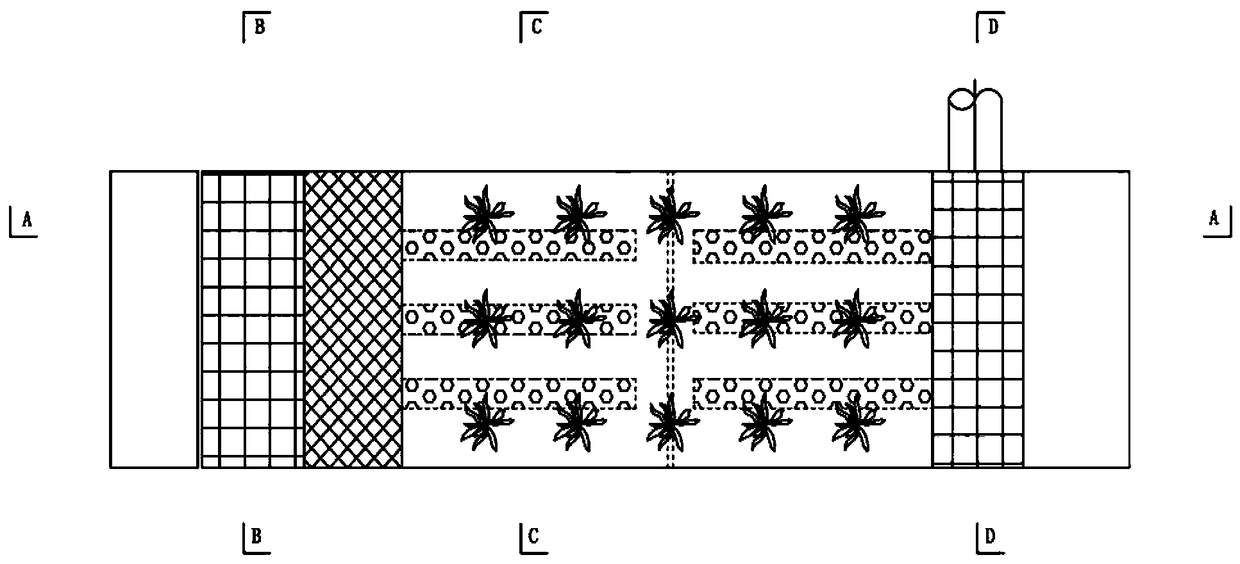
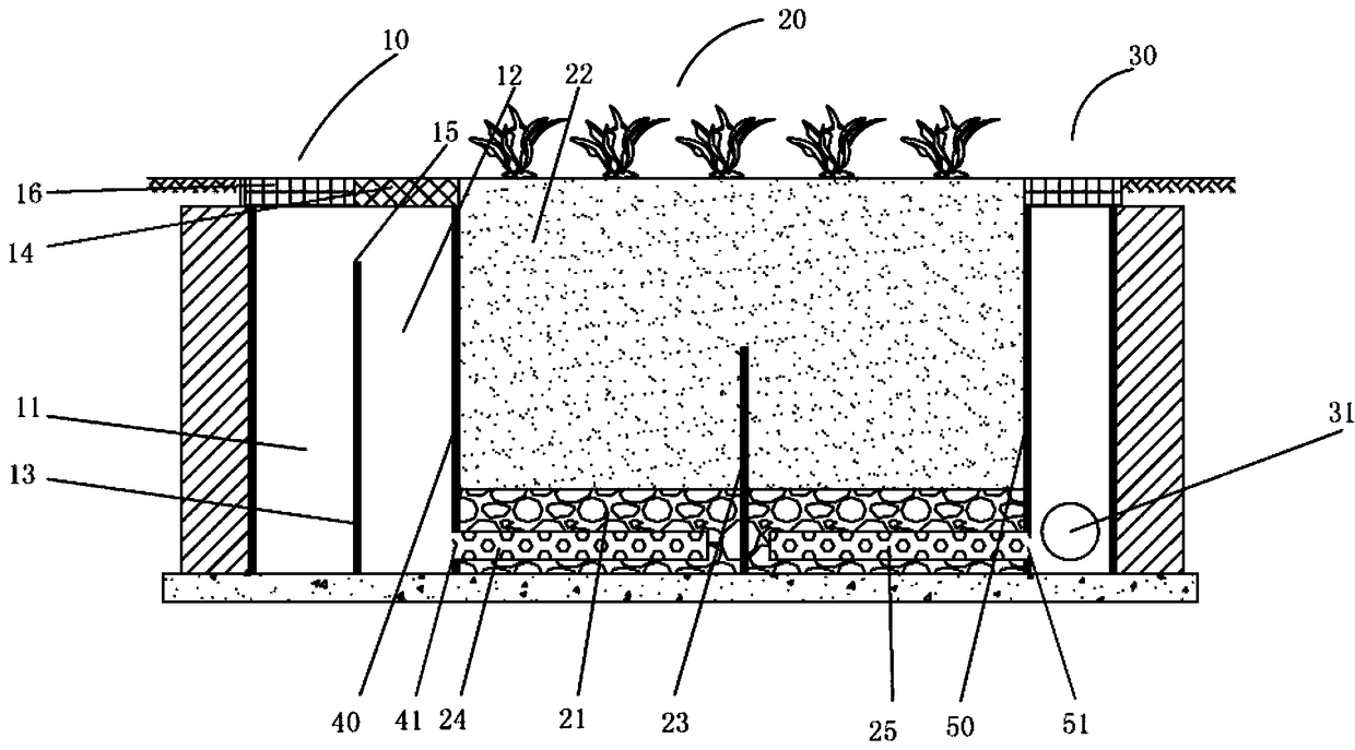
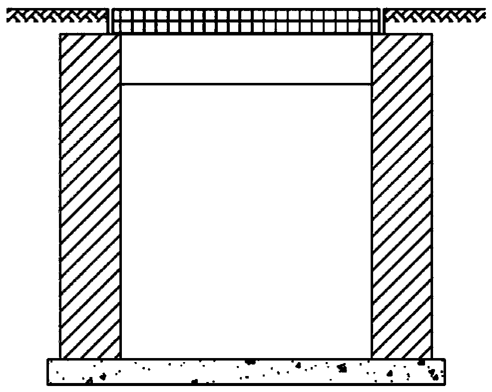
[0027] refer to Figure 1-Figure 5 , is a schematic diagram of a mixed-flow non-concave bioretention pond with the function of initial rainwater abandonment according to an embodiment of the present invention. The retention tank has a bottom and a side wall, the bottom of the retention tank is a concrete bottom, and the side wall is a cement mortar brick wall with a cement mortar plastering surface, concrete or polyvinyl chloride integrated molding material. The detention pond includes three parts: initial rainwater abandonment and distribution well 10 , detention pond main body 20 and overflow and outflow water collection well 30 . Among them, the initial rainwater abandonment and distribution well 10 is usually arranged at the water catchment at the edge of the road. The initial rainwater abandonment and distribution well 10 and the detention tank main body 20, between the detention tank main body 20 and the overflow and outflow collection well 30 are roughly divided into r...


PUM


Abstract

The invention discloses a mixed flow non-sunken bioretention pond having an initial rainwater discarding function. The retention pond comprises a bottom and sidewalls, and the retention pond is composed of three parts, namely an initial rainwater discarding and distributing well (10), a retention pond main body (20) and overflow and outflow water collecting well (30). Effective discarding and separating of initial rainwater can be achieved, and runoff pollution can be effectively controlled; a requirement on sinking downwards can be avoided, particulate pollutants in runoff entering facilitiescan be effectively relieved, the possibility that the bioretention pond gets blocked can be obviously reduced and efficient running of the facilities for a long term can be guaranteed; and through amixed flow mode combining 'upwards flowing and downwards flowing', overflowing paths of the runoff in the facilities are increased, and a control effect of the facilities over runoff pollution is obviously improved.

Description

technical field [0001] The invention belongs to the field of urban drainage and sponge city construction. Specifically, the invention relates to a mixed flow non-concave biological retention pond with the function of initial rainwater abandonment. Background technique [0002] Sponge city construction is an important measure to deal with a series of urban environmental problems such as urban waterlogging, black and odorous water bodies, and water ecological damage. As a typical facility in the source runoff control facilities of sponge city construction, rainwater bioretention facilities (also known as rain gardens) have multiple functions such as reducing the total amount of runoff at the source, delaying runoff peak discharge, and controlling runoff pollution. The application is very extensive. [0003] The runoff control of traditional bioretention facilities is to form an aquifer by sagging the surface of the facility by 200-300 mm to realize runoff stagnation. The rain...

Claims


Application Information

Patent Timeline
Patent Type & Authority Applications(China)
IPC IPC(8): E03F5/10E03F5/04E03F5/14C02F9/14C02F3/32
CPCC02F1/52C02F3/32C02F2103/001E03F5/0403E03F5/10E03F5/101E03F5/14E03F2201/10
Inventor 张伟钟兴车伍李俊奇孙超逸田笑尘高乐张郁媛
Owner BEIJING UNIV OF CIVIL ENG & ARCHITECTURE
Why Eureka
Try Eureka