
Fingerprint identification-based handle lock mechanism

A technology of fingerprint identification and handle lock, which is applied to locks controlled by non-mechanical transmission, building locks, building structures, etc. It can solve the problems that the file cabinet cannot be used directly, the fingerprint lock is large in size, and inconvenient to use, etc., and achieves fast and convenient fingerprinting. Recognition of unlocking and locking, small size, easy installation and operation

Inactive Publication Date: 2018-06-01
XIAN RENAN ELECTRONICS CONTROL TECH CO LTD
View PDF3 Cites 4 Cited by
  • Summary
  • Abstract
  • Description
  • Claims
  • Application Information

AI Technical Summary

Problems solved by technology

[0003] The cabinet locks or drawer locks in the prior art use traditional link locks, cam locks or linkage locks. If you need to replace them with fingerprint locks, you need to replace all the lock body parts. The operation is very complicated, and the existing fingerprint locks are relatively bulky. Large, cannot be replaced with the lock body on the filing cabinet or the drawer, and cannot be used directly on the filing cabinet. Even if it can be replaced, it is very inconvenient and expensive to use after replacement

Method used


Image

  • Fingerprint identification-based handle lock mechanism
  • Fingerprint identification-based handle lock mechanism
  • Fingerprint identification-based handle lock mechanism

Examples


Embodiment Construction

[0037]The present invention will be described in further detail below in conjunction with specific examples, but the embodiments of the present invention are not limited thereto.

[0038] In describing the present invention, it should be understood that the terms "center", "longitudinal", "transverse", "upper", "lower", "front", "rear", "left", "right", The orientations or positional relationships indicated by "vertical", "horizontal", "top", "bottom", "inner", "outer", etc. are based on the orientation or positional relationships shown in the drawings, and are only for the convenience of describing the present invention Creation and simplification of description, rather than indicating or implying that the device or element referred to must have a specific orientation, be constructed and operate in a specific orientation, and therefore should not be construed as limiting the invention.

[0039] In addition, the terms "first", "second", "third", etc. are used for descriptive p...


PUM


Abstract

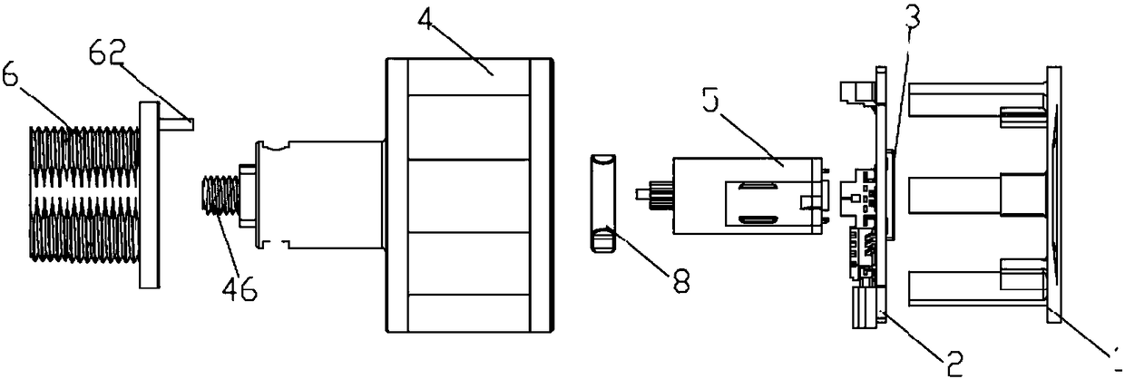
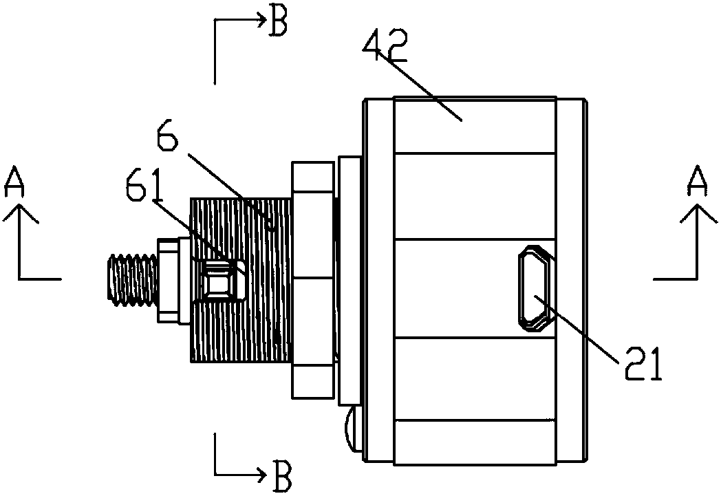
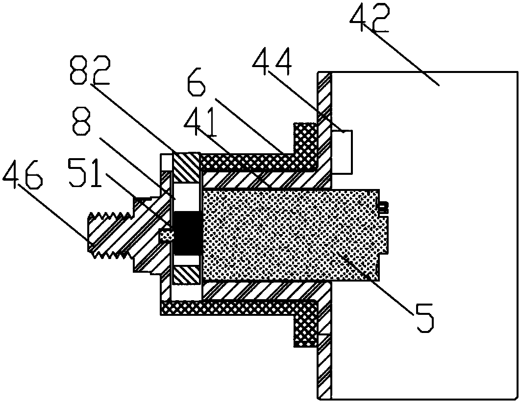
The invention relates to a fingerprint identification-based handle lock mechanism. The fingerprint identification-based handle lock mechanism comprises a face cover, a PCB (printed circuit board) arranged on the face cover, a fingerprint collecting module arranged on the PCB, and a movable handle case, wherein one end of the movable handle case is fixedly connected to the face cover, the other endof the movable handle case is provided with a fixing case fixedly connected with a lock hole, and the fixing case is in clearance fit with the movable handle case; the other end of the movable handlecase is fixedly connected with a lock plate; a motor is arranged inside the movable handle case; the inside of the other end of the movable handle case is provided with a locking piece, and the output shaft of the motor is connected with the locking piece. The fingerprint identification-based handle lock mechanism integrates fingerprint collection and fingerprint identification onto the PCB, anda locking clutch mechanism, a driving control device and the PCB inside the movable handle case, thereby being small in size and simple in structure. The fingerprint identification-based handle lock mechanism can replace the lock cylinder of a connecting rod lock, a cam lock, a blocking lock or the like, thereby being simple in installation and operation, increasing convenience of replacement of fingerprint lock and saving the cost. The fingerprint identification-based handle lock mechanism is simple in structure, saves costs and meanwhile achieves high reliability.

Description

technical field [0001] The invention belongs to the technical field of fingerprint lock equipment, and in particular relates to a handle lock mechanism based on fingerprint identification. Background technique [0002] Locks are indispensable accessories in daily life. There are many kinds of locks on the market, such as traditional mechanical locks and electronic locks. Fingerprint locks break the traditional mechanical lock's single door opening function. The fingerprint core algorithm technology is a high-tech product. The current fingerprint lock has many functions, such as networking function, door opening record function, remote control, intelligent alarm, multi-person mode, manager level and so on. [0003] The cabinet locks or drawer locks in the prior art use traditional link locks, cam locks or linkage locks. If you need to replace them with fingerprint locks, you need to replace all the lock body parts. The operation is very complicated, and the existing fingerpr...

Claims


Application Information

Patent Timeline
IPC IPC(8): E05B47/00E05B65/46E05B65/52E05C9/04G07C9/00
Inventor 史延东胡小合
Owner XIAN RENAN ELECTRONICS CONTROL TECH CO LTD
Learn More