Medium-wave infrared target simulation system using image space telecentric beam path

A technology of infrared target and telecentric optical path, which is applied in the field of infrared target simulation, can solve problems affecting target judgment, achieve the effect of suppressing cold reflection effect, improving image quality, and solving ghost image problems

Inactive Publication Date: 2018-06-01
HARBIN INST OF TECH +1
View PDF4 Cites 3 Cited by
  • Summary
  • Abstract
  • Description
  • Claims
  • Application Information

AI Technical Summary

Problems solved by technology

However, the traditional target simulator uses an objective lens with a common structure, and the cold light radiated by the cold grating will not return along the original optical path after being reflected by the resistance array, and the reflected cold light will be directly imaged on the detector CCD, forming a bright Spot (ie: ghost image), the bright spot is smaller than the target image, and superimposed with the target image on the detector CCD, affecting the target judgment
[0007] The cold reflection problem of the system generated in the above process means that the cold light emitted by the cold aperture of the detector itself is reflected back by the surface of the lens in the infrared optical system at the front end of the detector, and refocused on the photosensitive surface, causing its An imaging defect that detects self-cold images

Method used


Image

  • Medium-wave infrared target simulation system using image space telecentric beam path
  • Medium-wave infrared target simulation system using image space telecentric beam path
  • Medium-wave infrared target simulation system using image space telecentric beam path

Examples


specific Embodiment approach 1

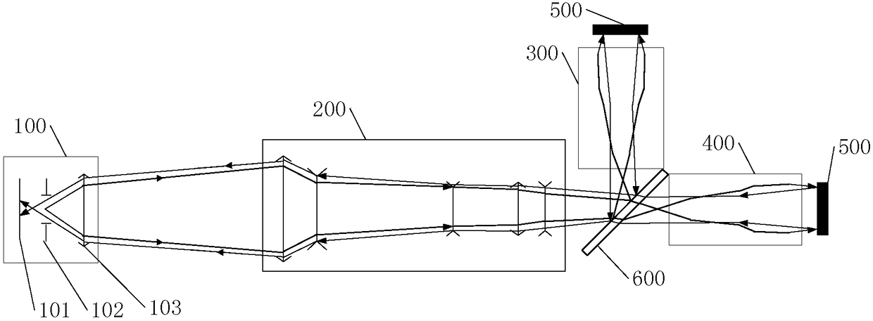
[0041] Specific implementation mode one: see figure 2 Describe this embodiment, a mid-wave infrared target simulation system that uses an image square telecentric optical path described in this embodiment, the target simulation system is used to generate an infrared simulation target whose target position is infinite, and is also used to make the infrared target The cold light radiated by the cold diaphragm 102 in the detector 100 is reflected by the target source and returns to the original path, forming an enlarged light spot on the detection surface 101 of the infrared target detector 100, and making the target image image on the detection surface with the enlarged light spot as the background 101 to eliminate the influence of ghost images on the target image;

[0042] Wherein, the target source includes an interference target source and a target source to be measured;

[0043]The formation process of the infrared simulation target is as follows: the interference target s...

specific Embodiment approach 2

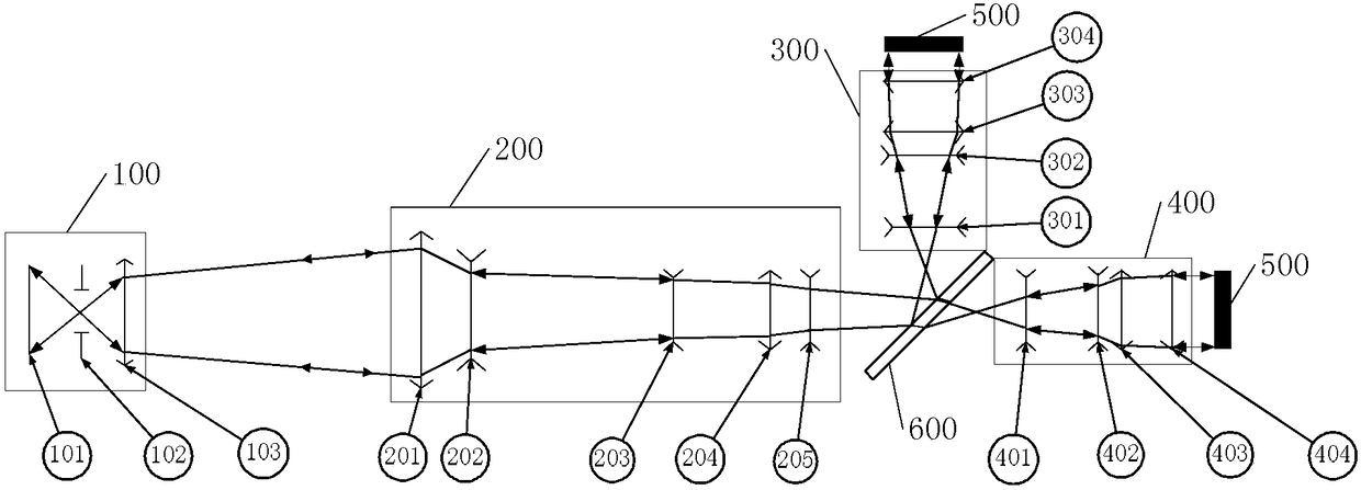
[0047] Specific implementation mode two: see Figure 2 to Figure 4 Describe this implementation mode. The difference between this implementation mode and the mid-wave infrared target simulation system using image telecentric optical path described in the first specific implementation mode is that the target simulation system includes an afocal beam expander system 200, a target straight line An objective lens 400, an interference collimating objective lens 300, two infrared emitting resistance array modules 500 and a coupling plate 600;

[0048] Wherein, an infrared emitting resistance array module 500 is used as an interference target source, and another infrared emitting resistance array module 500 is used as a target source to be measured;

[0049] The specific process of the target simulation system for generating an infrared simulation target with an infinite target position is:

[0050] After being transmitted by the interference collimating objective lens 300, the infr...

specific Embodiment approach 3

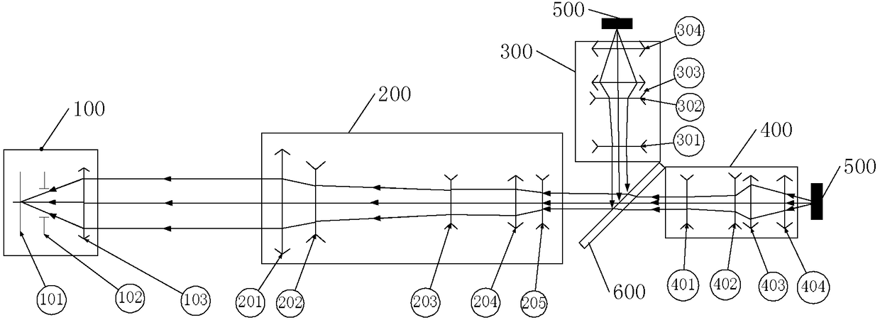
[0053] Specific implementation mode three: see Figure 2 to Figure 4 This embodiment is described. The difference between this embodiment and the mid-wave infrared target simulation system using the image square telecentric optical path described in the second specific embodiment is that the target simulation system is also used to make the infrared target detector 100 The cold light ray radiated by the cold diaphragm 102 in the infrared target detector 100 is reflected by the target source and returns to the original path, forming an enlarged light spot on the detection surface 101 of the infrared target detector 100, and making the target object image be imaged on the detection surface 101 with the enlarged light spot as the background, The specific process to eliminate the influence of ghost images on the target image is as follows:

[0054] The cold light radiated by the cold diaphragm 102 is concentrated and transmitted through the afocal beam expander system 200, and aft...


PUM


Abstract

The invention discloses a medium-wave infrared target simulation system using an image space telecentric beam path and belongs to the field of infrared target simulation. The problem that a light spot(ghost image) shown by cold light rays irradiated by a cold stop in an existing detection system on a detection face covers a target objective image, and the detection precision of the detection system is affected is solved. The target simulation system is used for generating a simulation target with the infinite the target position and is further used for making cold light rays irradiated by thecold stop in an infrared target detector return by the same way the cold light rays come through a target source, an amplified light spot is formed on the detection face of the infrared target detector, the target objective image is imaged on the detection face with the amplified light spot as the background, and the influences of the ghost image on the target objective image are eliminated. Thetarget source includes an interference target source and a to-be-detected target source. The forming process of the infrared simulation target includes that after the inference target source and the to-be-detected target source are coupled through the image space telecentric beam path, beam expanding is conducted, and therefore the infrared simulation target with the infinite target position is generated. The medium-wave infrared target simulation system is mainly used for generating the infrared simulation target.

Description

technical field [0001] The invention belongs to the field of infrared target simulation. Background technique [0002] The infrared target simulation system is an important part of the hardware-in-the-loop target simulation system, and the infrared target simulation is an indispensable link in both military and civilian fields. Due to the high cost of experiments required for physical object simulation and poor convenience, semi-physical object simulation has become the mainstream field of research in various countries, which is of great significance. [0003] Infrared targets are different from visible light targets. In the simulation process, the thermodynamic environment of the whole system is highly required. The identification, positioning and tracking of infrared targets have important research significance in both military and civilian fields. In order to realize the simulation of infrared targets in a more economical and efficient way, and at the same time facilitat...

Claims


Application Information

Patent Timeline
Patent Type & Authority Applications(China)
IPC IPC(8): F41G1/36G02B1/00G02B13/22
Inventor 张树青王治乐吴根水赵松庆屠宁王庆晨
Owner HARBIN INST OF TECH
Why Eureka
Try Eureka