Special-shaped radar combined decision target detecting method

A joint judgment and target detection technology, applied in radio wave measurement systems, instruments, etc., can solve the problems of long time-consuming registration parameter search, large data storage capacity, unknown target position and number, etc., and achieve the effect of improving the target detection probability

Active Publication Date: 2018-06-01
THE 724TH RES INST OF CHINA SHIPBUILDING IND
View PDF8 Cites 4 Cited by
  • Summary
  • Abstract
  • Description
  • Claims
  • Application Information

AI Technical Summary

Problems solved by technology

Since the sampling rate, resolution, precision, noise power level and other parameters of each radar device may be different, it is impossible to directly perform fusion / detection processing on multi-radar raw video data
In the document "Multi-radar Video Fusion System Design" (Master's Degree Thesis of Xidian University, 2009), a method of clustering and fusion of the same target video based on connected area marking is proposed, and the time-space alignment of the multi-radar video center is carried out. Using the idea of ​​clustering in pattern recognition theory, the center clusters the video centers of the same target under different radars, and then sends the target fusion center to the tracking system. Unable to confirm a valid target fusion center
In the document "Low Resolution Sea Radar Video Signal Registration Based on Mutual Information" (High Technology Communication, 2014, Vol.24, No.8, pp:800-806), the video signal was studied based on two sea radars The spatial characteristics of registration and its influencing factors are analyzed, the similarities and differences of target echo envelopes between different radars are analyzed, and a registration method based on mutual information is proposed, which is verified based on the measured data of S-band and C-band. The amount is large, and the registration parameter search takes a long time

Method used


Image

  • Special-shaped radar combined decision target detecting method
  • Special-shaped radar combined decision target detecting method
  • Special-shaped radar combined decision target detecting method

Examples


Embodiment Construction

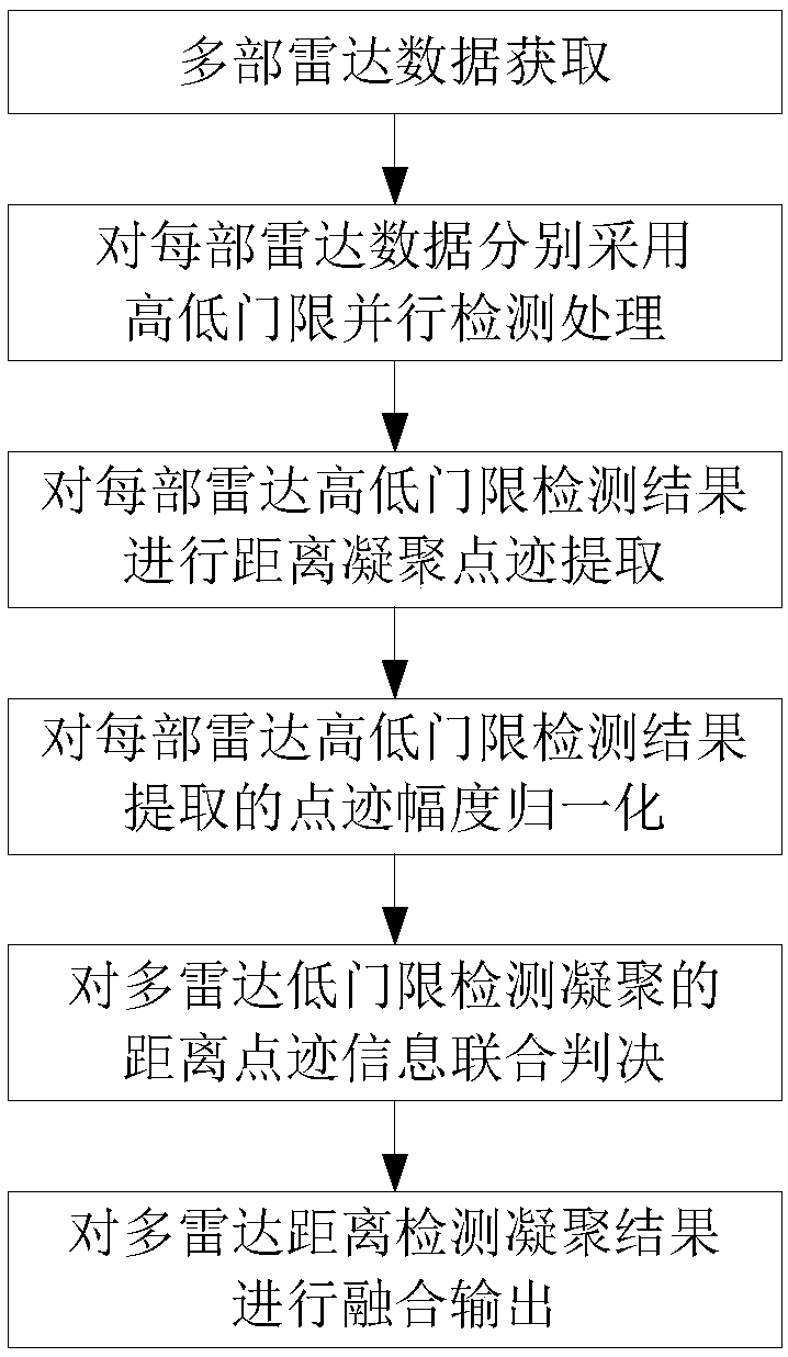
[0014] The processing flow of a special-shaped radar joint judgment target detection method of the present invention is as follows: figure 1 Shown, in conjunction with flow chart and embodiment, the embodiment of the method of the present invention is set forth in detail, and process is as follows:

[0015] Step 1: Multiple radar data acquisition.

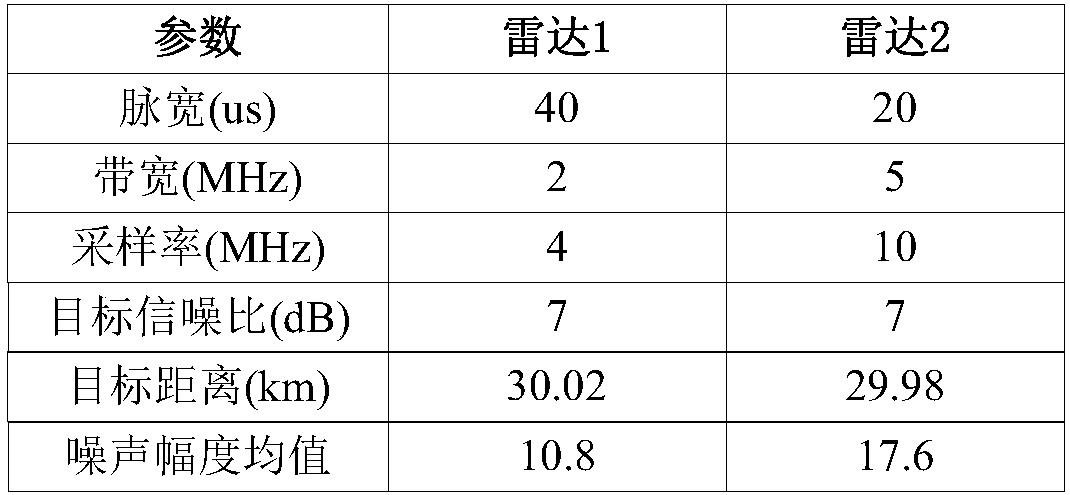
[0016] Let the original video data of multiple radars acquired at the same time be f MTP (n,i),n=1,...,N radar ,i=1,...,N range_n , where N radar is the number of radars on the same platform, N range_n is the number of sampling points for the distance of the nth radar.

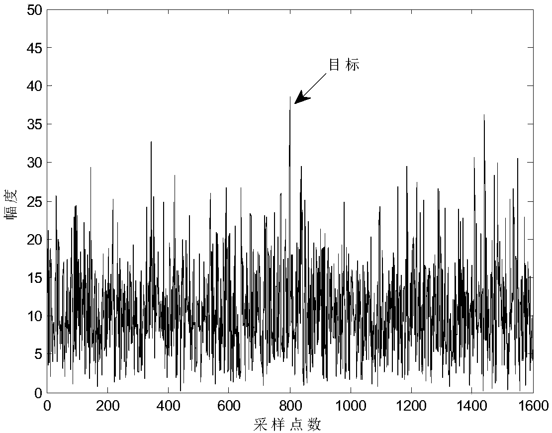
[0017] Step 2: High and low threshold detection.

[0018] According to the actual false alarm probability, set the high threshold detection coefficient as γ 1 , the low threshold detection coefficient is γ 2 , respectively using the threshold coefficient γ 1 and gamma 2 Parallel CFAR detection is performed on each radar data, and the amplitude value is re...


PUM


Abstract

The invention provides a special-shaped radar combined decision target detecting method. A high threshold and a low threshold are utilized for performing CFAR detection on original video data of eachradar. After performing high-threshold detection and low-threshold detection on each data, a distance condensation point trace is extracted from the data. Normalization is performed on the point traceamplitude according to distance point trace local signal clutter/noise ratio and the noise substrate of each radar. Combined detection and decision is performed on the low-threshold detection condensation point traces of all radars according to a radar distance measurement error. Furthermore the high-threshold detection condensation point traces of multiple radars are combined, thereby finishingoriginal-video-grade multiple-radar combined target detection processing. According to the method of the invention, the high threshold and the low threshold are utilized, thereby improving target detection probability. For each radar, the distance point trace is extracted and then combined determining is performed, thereby preventing a problem of direct fusion processing incapability caused by different multiple-radar sampling rates, different resolutions, different noise substrates and the like.

Description

technical field [0001] The invention belongs to the technical field of radar target detection. Background technique [0002] The increasingly complex electromagnetic environment makes single-radar target detection more and more challenging. Multiple radar devices installed on the same platform can be dispatched through reasonable time, frequency, energy and other aspects under the condition of task arrangement permission. Realize joint target detection, improve target detection capability, and have great application potential in engineering, mainly reflected in two aspects: First, multiple radar data on the same platform can realize real-time data transmission and communication through optical fiber or network. Interaction, there are many problems that need to be considered in remote data transmission; second, the position information of multiple radars located on the same platform is clear, the coordinates are unified, and spatial synchronization and position registration a...

Claims


Application Information

Patent Timeline
Patent Type & Authority Applications(China)
IPC IPC(8): G01S7/02
CPCG01S7/021
Inventor 夏永红匡华星丁春姚远
Owner THE 724TH RES INST OF CHINA SHIPBUILDING IND
Why Eureka
Try Eureka