
A method for controlling axial velocity and density ratio of planar cascade

A technology of axial speed and control method, applied in design optimization/simulation, special data processing application, CAD numerical modeling, etc., can solve the problems of fluctuating incoming flow conditions, large suction flow, and blade cascade changes, etc. The effect of strong adaptability to the environment, simple suction structure and small flow field disturbance

Active Publication Date: 2021-10-01
AECC SHENYANG ENGINE RES INST
View PDF10 Cites 0 Cited by
  • Summary
  • Abstract
  • Description
  • Claims
  • Application Information

AI Technical Summary

Problems solved by technology

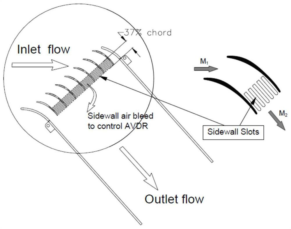
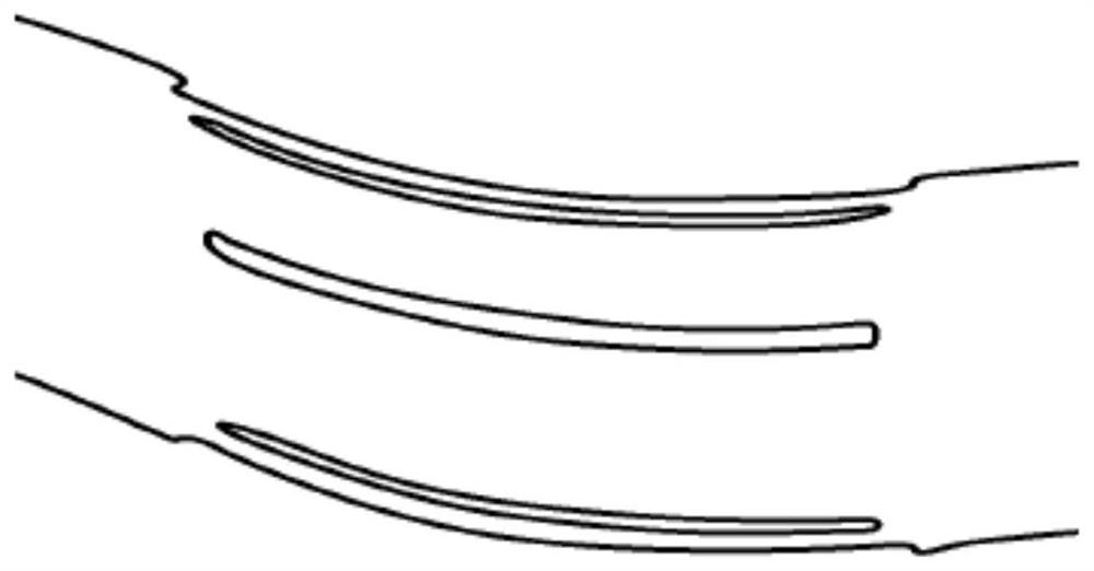
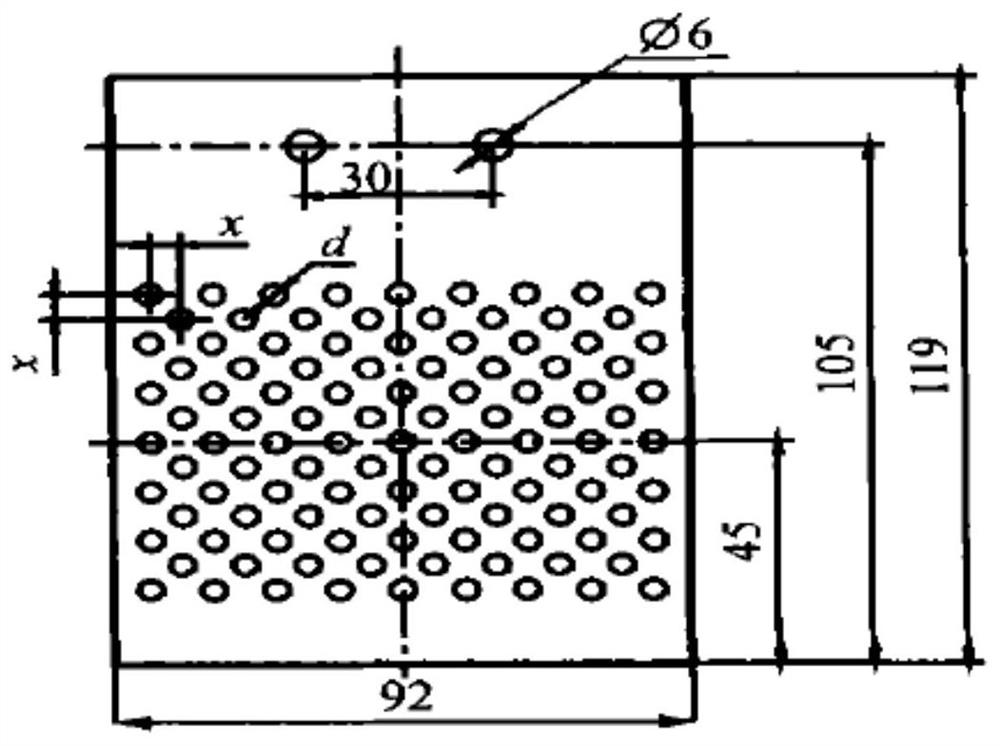
figure 1 The suction flow rate of the scheme is large, and small changes in the back pressure of the suction chamber are likely to cause large fluctuations in the flow conditions; and figure 1 Compared to the scheme, figure 2 The suction volume of the scheme is reduced and the adaptability to working conditions is stronger, but the suction position covers the separated low-velocity area, resulting in excessive suction flow and fluctuating incoming flow conditions, and the suction groove is too close to the front edge, which will cause Variation of the actual airflow angle of the cascade; image 3 The determination of the opening area, aperture, arrangement and opening ratio of the scheme is the most complicated. On the one hand, too many suction holes will cause excessive suction flow, which will cause great changes in the flow conditions and affect the test accuracy. On the one hand, the suction hole itself is a disturbance source, and too many suction holes may make the flow worse when disturbing the mainstream flow field

Method used


Image

  • A method for controlling axial velocity and density ratio of planar cascade
  • A method for controlling axial velocity and density ratio of planar cascade
  • A method for controlling axial velocity and density ratio of planar cascade

Examples


Embodiment Construction

[0025] In order to make the objects, technical solutions, and advantages of the present invention, the technical solutions in the embodiments of the present invention will be described in more detail below in connection with the drawings of the embodiments of the present invention. In the drawings, the same or similar components or elements having the same or similar functions are represented by the same or similar reference numerals. The described embodiments are examples of the embodiments of the invention, not all embodiments. The following is exemplary, and is intended to be used to illustrate the invention without understanding the limitation of the invention. Based on the embodiments of the present invention, those of ordinary skill in the art will belong to the scope of the present invention without all other embodiments obtained without creative labor.

[0026] The planar blades of the present invention will be further described in detail below with reference to the accomp...


PUM


Abstract

The invention provides a method for controlling the axial velocity density flow ratio of a plane cascade. The steps are as follows: establish a numerical simulation model of a target plane cascade and divide the calculation grid; Perform numerical simulation on the characteristics of the angle of attack to obtain the starting point of the positive and negative stall angle of attack and the separation of the angle zone, and determine the length of the suction area; establish a series of suction area calculation models with different widths and divide the numerical calculation grid; Under the stall angle of attack, the suction effect of suction areas with different widths is numerically simulated, and the optimal suction area width is determined by comparison and analysis. The method provided by the present invention effectively suppresses the angular separation of the planar cascade under different incoming flow Mach numbers and attack angles, controls the axial velocity density ratio of the planar cascade within the range of 0.98-1.05, and ensures the duality of flow .

Description

Technical field [0001] The present invention belongs to the field of compressor planar blade hair dryer test, and in particular, the present invention relates to the field of end wall suction structures to control the flow control field, and more particularly to a planar blade axial veloelectrode flow ratio control method. Background technique [0002] Endwall suction is an important method for controlling the axial velocity of planar blade. The development of the corner end wall with the end wall suction is reduced or eliminated by the angular region separation of the blade grid, thereby achieving control of the axial veloelectric delux ratio. The existing planar leaf-end wall suction scheme is suction in the plane of the plane of the flat leaf grating, respectively ( figure 1 ), Draw a whole slot along the whole sinus long ( figure 2 ) And porous wall suction ( image 3 ). figure 1 The suction flow rate of the solution is large, and the small change of suction chamber back press...

Claims


Application Information

Patent Timeline
Patent Type & Authority Patents(China)
IPC IPC(8): G06F30/23G06F111/10
CPCG06F30/23
Inventor 史文斌朱振坤潘若痴孟德君李昊
Owner AECC SHENYANG ENGINE RES INST
Learn More