
Method for predicting fatigue service life of water pump vane and confirming optimal space with guide vane

A technology for prediction and determination of fatigue life, applied in pump control, non-variable-capacity pumps, design optimization/simulation, etc.

Active Publication Date: 2018-06-01
YANGZHOU UNIV
View PDF9 Cites 3 Cited by
  • Summary
  • Abstract
  • Description
  • Claims
  • Application Information

AI Technical Summary

Problems solved by technology

[0002] Axial flow pumps and guide vane mixed flow pumps have the characteristics of high specific speed, large flow, and low head. They are mainly used in fields such as agricultural irrigation and drainage, sewage discharge, water transfer, thermal power plants and nuclear power cooling and circulating water. The impeller blades are water pumps The core component of energy conversion, in order to meet the needs of operation, the installation angle of the blade can be adjusted. The blade is fixed by inserting the blade shaft at the root into the hub of the impeller. It is a cantilever structure. When the water pump is running, due to the dynamic and static interference of the guide vane not far from the blade outlet The pressure pulsation occurs on the surface of the blade, and the blade generates alternating stress under a large stress level. In actual production, cracks or even serious accidents often occur in the blade of the water pump, and the life of the blade is far lower than its rated life. , leading to frequent fatigue fracture accidents, affecting the normal operation and function of the pump

Method used


Image

  • Method for predicting fatigue service life of water pump vane and confirming optimal space with guide vane
  • Method for predicting fatigue service life of water pump vane and confirming optimal space with guide vane
  • Method for predicting fatigue service life of water pump vane and confirming optimal space with guide vane

Examples


Embodiment Construction

[0076] Below in conjunction with accompanying drawing and embodiment the present invention will be further described:

[0077] A large vertical axial flow pump in a pumping station, impeller diameter 1640mm, impeller hub diameter 820mm, blade design angle 0°, speed 250r / min, pump device design head 6m, design flow rate 10.6m 3 / s, blade angle adjustment range: -4°~+6°. The blade is made of stainless steel ZG1Cr18Ni9Ti, and its material properties are shown in Table 7:

[0078] The material property of table 7 embodiment blade

[0079]

[0080] The structure of the water pump impeller and guide vane, as well as the performance curve of the pump device are known.

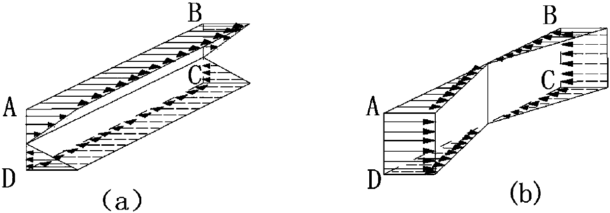
[0081] A Determination of the dangerous section and dangerous point of the fatigue fracture of the water pump blade:

[0082] Such as figure 1 As shown, from the perspective of static force, point A on the inlet side of the upper edge of the connection between the root section of the blade and the hub is superi...


PUM


Abstract

The invention discloses a method for predicting fatigue service life of a water pump vane and confirming optimal space with a guide vane, and belongs to the technical field of reliable durability of apower machinery device. the method includes confirmation of fatigue rupture hazardous section and hazardous points of the water pump vane, fluid field numerical value simulation in different workingconditions of the water pump and CFD calculation of impulse water pressure distribution of vane surface; calculation of hazardous point alternating stress at root section of water pump vane; calculation of fatigue service life of vane under different working conditions of water pump; calculation of alternating stress and fatigue service life of vane hazardous point when the space between the waterpump vane and the guide vane is different; replacement, dismounting and overhaul costs for comprehensively considering the vane fatigue rupture in service life of water pump; influence of water pumpefficiency change caused by space change on running cost; influence of axial dimension of water pump on installing layout; final determination of optimal space between vane and the guide vane. The method can exactly predict the fatigue service life of the axial flow pump and the guide vane type mixed flow pump vane, optimize the space between the vane and the guide vane, and improve the vane fatigue durability.

Description

technical field [0001] The invention belongs to the technical field of reliability and durability of power mechanical equipment, and relates to a method for predicting blade fatigue life and determining the optimal distance between the guide vane and the guide vane under the full operating conditions of an adjustable axial flow pump and a guide vane mixed flow pump. It is the prediction and calculation of the fatigue fracture life of the blade due to the dynamic and static interference with the guide vane when the water pump is running at different lifts and different blade angles. The optimal blade and guide vane are determined by comprehensively considering the fatigue fracture life of the blade, the energy performance of the water pump and the axial size of the water pump. method of spacing. Background technique [0002] Axial flow pumps and guide vane mixed flow pumps have the characteristics of high specific speed, large flow, and low head. They are mainly used in field...

Claims


Application Information

Patent Timeline
IPC IPC(8): G06F17/50F04D15/00
CPCF04D15/0088G06F30/23G06F2119/04
Inventor 仇宝云曹金玉黄先北郭嫱汤黎明许梦凡薛成龙张偲刘地
Owner YANGZHOU UNIV
Learn More