Demonstration instrument for extension and retraction process of aircraft landing gear

An aircraft landing gear and demonstrator technology, which is applied in the field of teaching instruments, can solve the problems of not being able to fully demonstrate the entire process of retracting and retracting the aircraft landing gear, not being equipped with a landing gear door, and unable to carry out the aircraft landing gear, etc. Conducive to classroom teaching demonstration, light weight effect

Pending Publication Date: 2018-06-01
TIANJIN SINO GERMAN VOCATIONAL TECHNICAL COLLEGE
View PDF0 Cites 0 Cited by
  • Summary
  • Abstract
  • Description
  • Claims
  • Application Information

AI Technical Summary

Problems solved by technology

[0003] In the teaching of aviation professional courses, it is difficult for students to have a good understanding of the composition and working process of fixed-wing aircraft landing gear through existing teaching methods such as textbooks, pictures, and videos
Although some training sites are equipped with aircraft, it is not possible to demonstrate the retraction and retraction of the aircraft landing gear
Moreover, the existing aircraft landing gear teaching aids are generally refitted with decommissioned aircraft landing gears, which are bulky, heavy, and occupy a large floor area; they have single functions, generally only have the landing gear body, and are not configured to be related to the retracting and retracting process of the landing gear. The landing gear hatch cannot fully demonstrate the whole process of retracting and retracting the aircraft landing gear

Method used


Image

  • Demonstration instrument for extension and retraction process of aircraft landing gear
  • Demonstration instrument for extension and retraction process of aircraft landing gear
  • Demonstration instrument for extension and retraction process of aircraft landing gear

Examples


Embodiment Construction

[0028] In order to enable those skilled in the art to better understand the technical solutions of the present invention, the present invention will be further described in detail below in conjunction with the accompanying drawings and preferred embodiments.

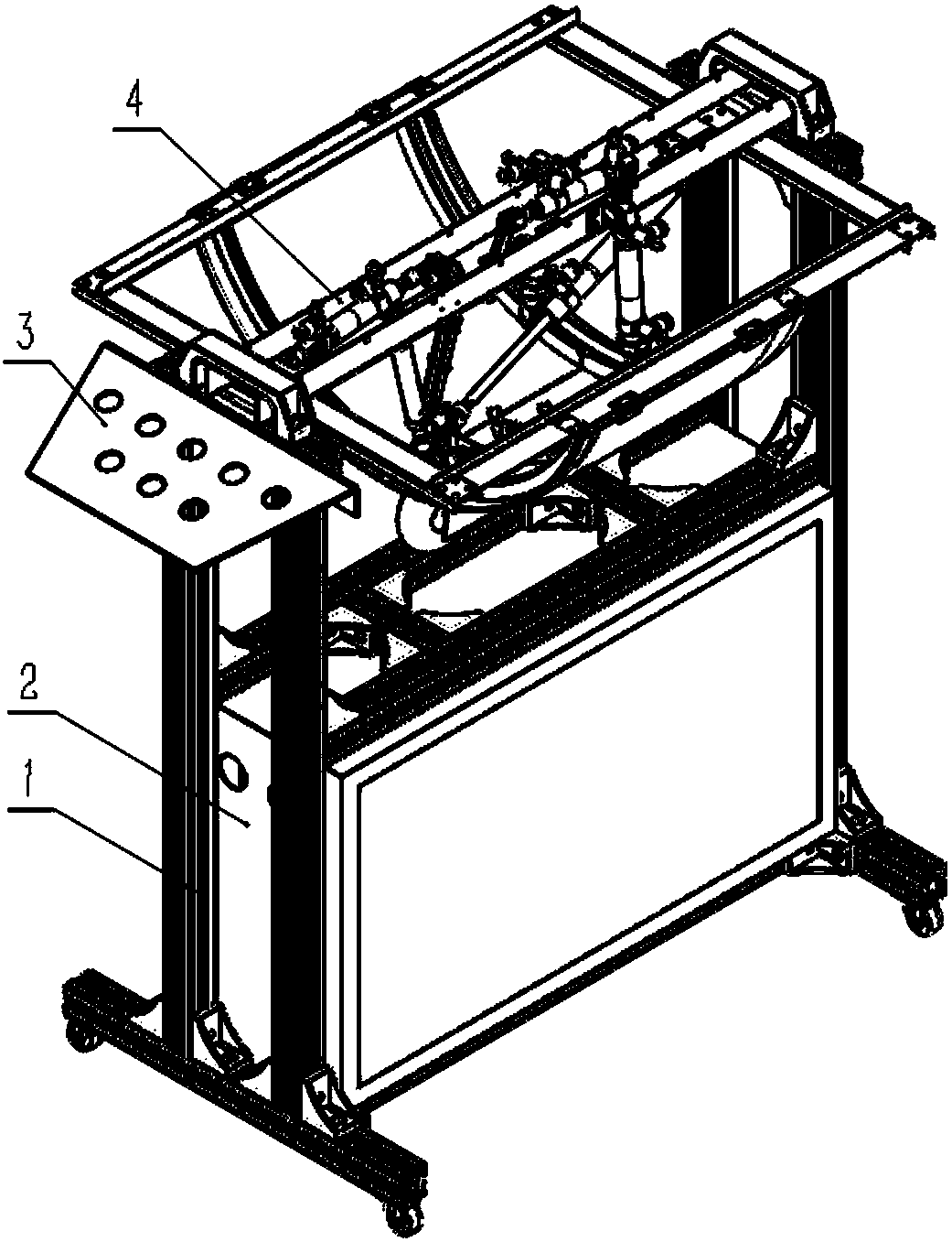
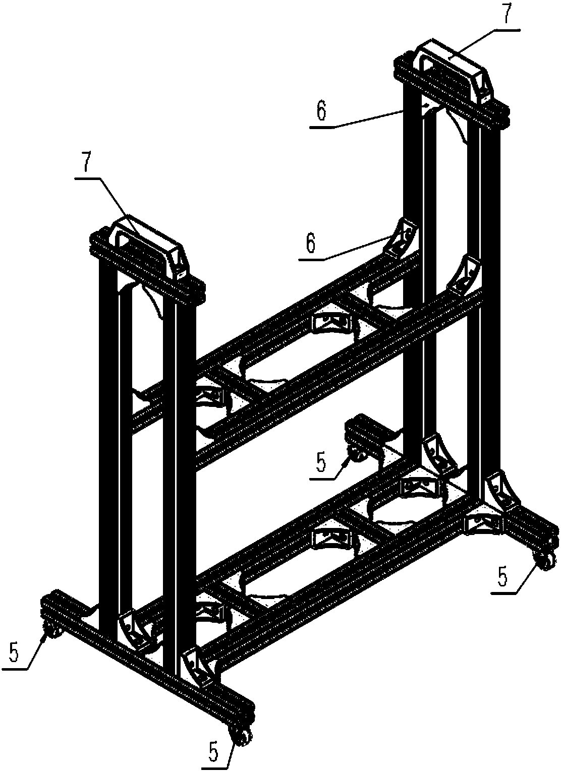
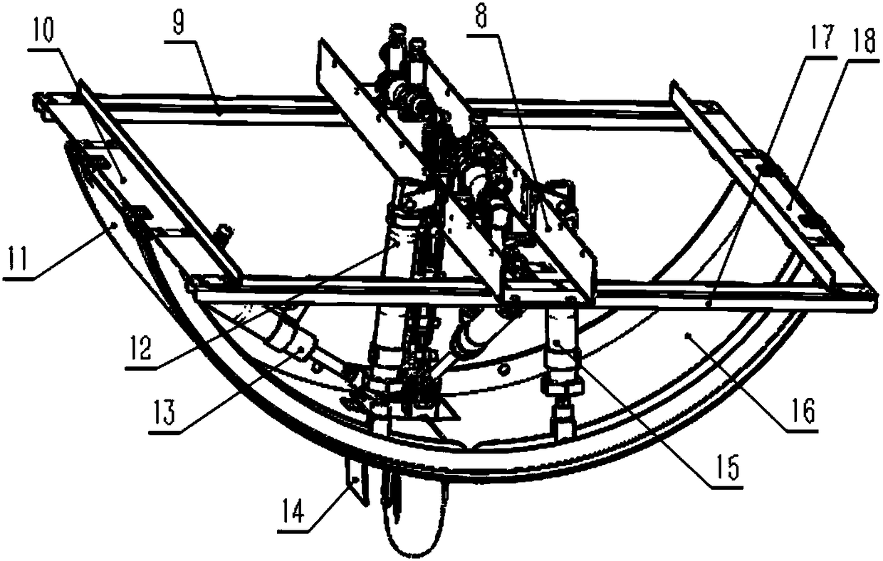
[0029] Figure 1-4 Shown is an aircraft landing gear retractable process demonstrator, including a support device, a control device and a body demonstration device; the body demonstration device includes a wheel retractable demonstration device and a landing gear retractable demonstration device; the landing gear The retractable demonstration device includes a fuselage frame and a retractable unit arranged on the fuselage frame; the fuselage frame includes a central longitudinal main beam 8, symmetrically arranged on the left and right sides of the central longitudinal main beam The left longitudinal beam 10 and the right longitudinal beam 18, and the front beam 9 and the rear beam 17 arranged on the front and rear sides...


PUM


Abstract

The invention belongs to the field of teaching apparatuses, and in particular relates to a demonstration instrument for the extension and retraction process of an aircraft landing gear. The demonstration instrument comprises a support device, a control device and a body demonstration device, wherein the body demonstration device comprises an aircraft wheel extension and retraction demonstration device and a landing gear extension and retraction demonstration device; an extension and retraction unit comprises a left main cabin door demonstration mechanism and a right main cabin door demonstration mechanism which are symmetrically arranged on the left and right sides of a central longitudinal main beam; the left main cabin door demonstration mechanism comprises a left main cabin door and a left main cabin door drive air cylinder; one end of the left main cabin door is hinged to the edge of a left longitudinal beam, and the other end of the left main cabin door is hinged to one end of theleft main cabin door drive air cylinder; the other end of the left main cabin door drive air cylinder is hinged to the left end face of the central longitudinal main beam. The demonstration instrument is simple in structure, small in size, light in weight, and convenient and reliable to use, and belongs to the teaching apparatus capable of being widely applied to the demonstration of the extension and retraction process of the aircraft landing gear.

Description

technical field [0001] The invention belongs to the field of teaching instruments, in particular to an aircraft landing gear retractable process demonstrator. Background technique [0002] The landing gear system of fixed-wing aircraft is one of the most complex systems on the aircraft, and its working performance directly affects the stability and safety of the aircraft take-off and landing. The process of retracting and lowering the landing gear must execute a series of complex actions in a strict order within a specified time. [0003] In the teaching of aviation professional courses, it is difficult for students to have a better understanding of the composition and working process of fixed-wing aircraft landing gear through existing teaching methods such as textbooks, pictures, and videos. Although some training sites are equipped with aircraft, it is not possible to demonstrate the retraction and retraction of the aircraft landing gear. Moreover, the existing aircraft...

Claims


Application Information

Patent Timeline
IPC IPC(8): G09B25/02
CPCG09B25/02Y02T50/40
Inventor 张建新张兴会武晋宋玲玲
Owner TIANJIN SINO GERMAN VOCATIONAL TECHNICAL COLLEGE
Why Eureka
Try Eureka