Rotor punching sheet for permanent-magnet motor of electric vehicle

A technology of rotor punching and permanent magnet motors, which is applied in the direction of electric vehicles, motors, electric components, etc., can solve the problems of reducing reluctance torque components, low production efficiency, and reducing salient pole ratio, so as to reduce torque ripple, The effect of improving production efficiency and reducing harmonics

Pending Publication Date: 2018-06-01
山东双林新能源科技有限公司
View PDF11 Cites 10 Cited by
  • Summary
  • Abstract
  • Description
  • Claims
  • Application Information

AI Technical Summary

Problems solved by technology

However, the permanent magnet synchronous motor described in this scheme is a permanent magnet motor with fractional slots and "one"-shaped magnets. As mentioned above, although the fractional slot structure is conducive to reducing torque fluctuations, due to the winding characteristics of the fractional slots, it will More sub-harmonics and fractional harmonics will be introduced in the air-gap magnetic field, which may cause serious NVH problems, and the "one"-shaped magnets have not fully utilized the non-uniform reluctance caused by the orthogonal and direct axes. Reluctance torque, its weak field speed expansion performance is also poor, not suitable for electric vehicle drive motors that need to operate in a wide speed range
[0011] The patent application number is 201510587869.5, which refers to a rotor, a permanent magnet synchronous motor including the rotor and an electric vehicle. The solution is to set a plurality of bosses between every two adjacent magnetic steels on the circumferential surface of the rotor body , to optimize the air-gap magnetic field waveform, but the boss structure of this scheme substantially increases the air-gap length of the motor. In order to ensure a considerable power density, more magnetic steel materials are bound to be used, and the overall cost will increase greatly. Not conducive to future marketing
[0012] The patent application No. 201510667043.X refers to a magnetic steel rotor and a permanent magnet synchronous motor. This solution substantially reduces the salient pole ratio. Although the torque fluctuation is reduced, the reluctance torque component is also reduced at the same time. As a result, Resulting in reduced power density and reduced speed range
[0013] The patent application No. 201510797828.9 refers to a permanent magnet synchronous motor rotor driven by an electric vehicle. This solution is a rotor with a wrong pole structure. As mentioned above, it will also bring about the complexity of the iron core process, requiring additional Fixtures and fixtures, and low production efficiency
[0014] In summary, torque ripple is one of the performance indicators that must be considered in the permanent magnet drive system of electric vehicles. For automotive drive motors, it is best to find a new rotor without increasing manufacturing difficulty and material cost. Structural design forms to achieve the goal of reducing harmonics and torque ripple. Therefore, there are problems and deficiencies in the prior art that need to further reduce harmonics, reduce torque ripple, improve efficiency, and reduce costs.

Method used


Image

  • Rotor punching sheet for permanent-magnet motor of electric vehicle
  • Rotor punching sheet for permanent-magnet motor of electric vehicle
  • Rotor punching sheet for permanent-magnet motor of electric vehicle

Examples


Embodiment Construction

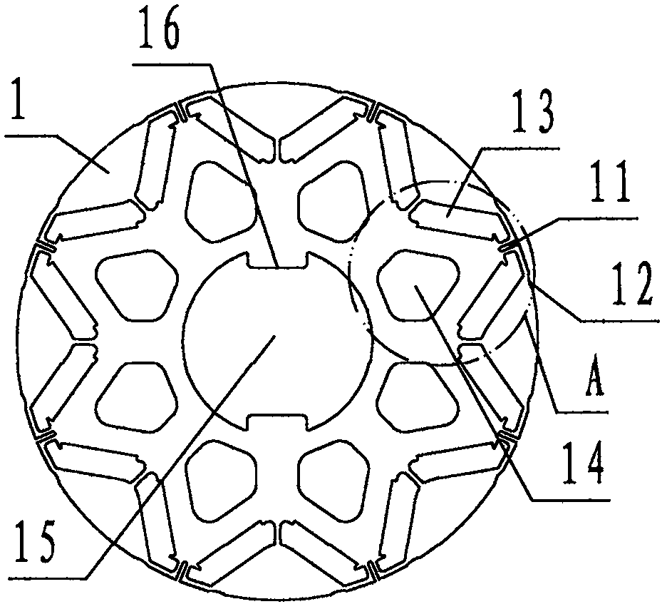
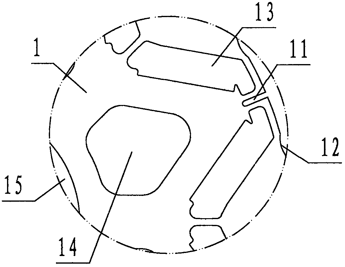
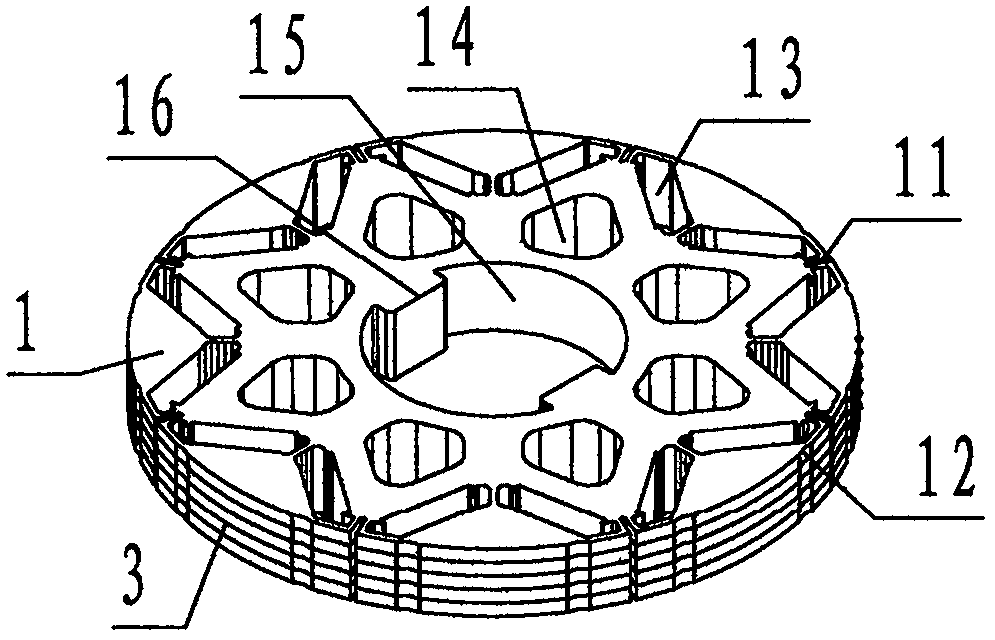
[0032] refer to Figure 1 ~ Figure 4 , a permanent magnet motor rotor punching sheet for an electric vehicle of the present invention, the rotor punching sheet is provided with a magnetic isolation groove 11, a magnetic gap notch 12, a permanent magnet hole 13, a weight reduction hole 14, a shaft hole 15 and a tenon key 16 The film base 1 is composed of; the film base 1 is an alloy permeable soft magnetic member with an insulating paint film and a circular thin sheet on the surface, and the center of the film base 1 is provided with a circular through hole called a shaft hole 15 , the upper and lower sides of the shaft hole 15 are provided with rectangular flanges called mortise keys 16; An octagonal star-shaped magnetic pole circle, the permanent magnet hole 13 is a rectangular through hole in the shape of a ∫ character; The through hole is called the weight-reducing hole 14; at the circumference of the base 1, there is a rectangular gap between two adjacent permanent magnet...


PUM


Abstract

The invention discloses a rotor punching sheet for a permanent-magnet motor of an electric vehicle. The rotor punching sheet comprises a sheet base (1), wherein the sheet base (1) is provided with magnetic isolation grooves (11), magnetic gap notches (12), permanent-magnet holes (13), weight reduction holes (14), a rotation shaft hole (15) and tenon keys (16). During application, a plurality of sheet bases are correspondingly superposed to form a rotor core, the rotation shaft hole is used for fixedly connecting a rotor shaft, the permanent-magnet holes are used for fixedly bearing permanent magnets, and thus, a permanent-magnet motor rotor is formed; during working and on the basis of a principle that air reluctance larger than iron core reluctance, the magnetic isolation grooves are usedfor improving reluctance, magnetic short-circuit is reduced, and the output power of the permanent-magnet motor rotor is improved; the magnetic gap notches are used for balancing distribution densityof a magnetic line, local enrichment of the magnetic line is suppressed, the torque pulse amplitude of the permanent-magnet motor rotor is reduced, and the torque fluctuation is smoothed; and the weight reduction holes are used for reducing weight and material cost, the technical scheme of an air-cooling passage of a cooling rotor is formed, so that the permanent-magnet motor of the electric vehicle achieves the purposes of reducing harmonic, torque pulse and cost and improving efficiency.

Description

technical field [0001] The invention relates to a driving motor of an electric vehicle, in particular to a stamped sheet of a permanent magnet motor rotor of an electric vehicle used for lamination to form a permanent magnet motor rotor of the electric vehicle. Background technique [0002] The rotor punch described in this paper is a sheet-shaped, alloy permeable soft magnetic component that is laminated to form the permanent magnet motor rotor of an electric vehicle. The soft magnetic is a magnetic material with low coercive force and high magnetic permeability. [0003] Permanent magnet motors have the characteristics of high torque density, low manufacturing cost, and wide high-efficiency area. They are the first choice for driving motors for new energy vehicles such as hybrids, pure electric vehicles, and fuel cells. The torque of the rotor rotating with the rotating electromagnetic field of its stator coil windings produces pulsations, referred to as torque fluctuation...

Claims


Application Information

Patent Timeline
Patent Type & Authority Applications(China)
IPC IPC(8): H02K1/27
CPCH02K1/2706H02K2213/03Y02T10/64
Inventor 曹翼孙丹孙文举
Owner 山东双林新能源科技有限公司
Why Eureka
Try Eureka