Gate resonant part and gate resonant device

A component and resonance technology, applied in the field of electron tubes, can solve problems such as inability to match tetrodes, low precision, and slow speed

Active Publication Date: 2021-06-08
BEIJING CHANGFENG BROADCASTING COMM EQUIP
View PDF5 Cites 0 Cited by
  • Summary
  • Abstract
  • Description
  • Claims
  • Application Information

AI Technical Summary

Problems solved by technology

[0005] In view of this, an embodiment of the present invention provides a grid resonant component and a grid resonant device to solve the problem of using a motor to adjust the output inductance of the variable inductor in the prior art, so that the output inductance and the grid of the tetrode The current way of inherent capacitance to generate resonance, low precision and slow speed, can not match the technical defects of tetrodes working in the radio frequency range

Method used


Image

  • Gate resonant part and gate resonant device
  • Gate resonant part and gate resonant device
  • Gate resonant part and gate resonant device

Examples


Embodiment 1

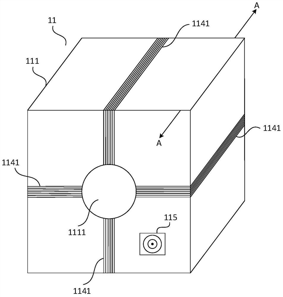
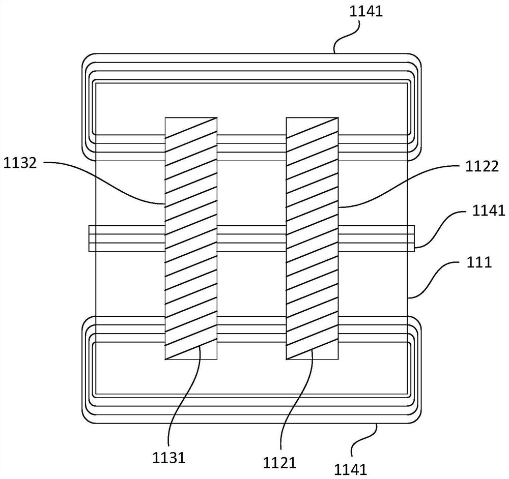
[0072] Figure 1a It is a front view of a gate resonant component 11 provided in Embodiment 1 of the present invention. The grid resonant component 11 of this embodiment specifically includes: a casing 111 , a first inductive component 112 , a second inductive component 113 , a third inductive component 114 and a signal input socket 115 .

[0073] Wherein, the shape of the housing 111 may specifically be a cube, a sphere, a cylinder or a cone, etc., which is not limited in this embodiment. Figure 1a The shape of the casing 111 is exemplarily represented as a cube in . The material of the housing 111 can be specifically iron, copper or plastic, and this embodiment does not limit it, but if the signal input through the signal input socket 115 is a high-frequency signal, the material of the housing 111 is preferably iron. Because the iron casing 111 has a better shielding effect on high-frequency signals, it can effectively prevent high-frequency signals from radiating to the ou...

Embodiment 2

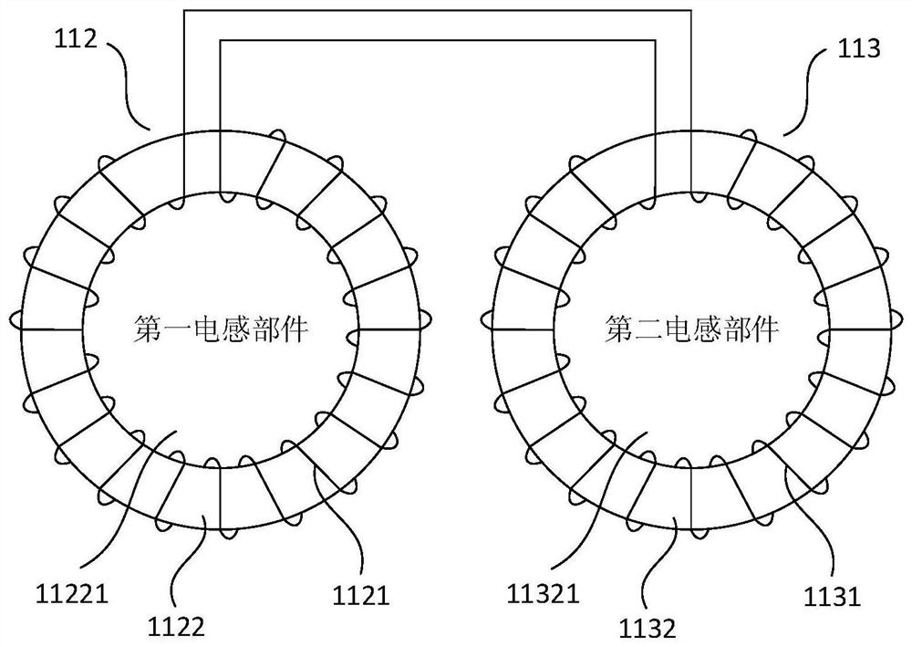
[0092] figure 2 It is a front view of a gate resonant component 11 provided in Embodiment 2 of the present invention. This embodiment is optimized on the basis of the above embodiments. In this embodiment, the first inductance component 112 is optimized to further include: a first insulator 1123, and the first insulator 1123 covers the outer surface of the first ferrite 1122 ; The second inductance component 113 is optimized to further include: a second insulator 1133 covering the outer surface of the second ferrite 1132 ;

[0093] Correspondingly, the first coil 1121 is evenly wound on the first ferrite 1122 through the second through hole 11221 , which is optimized as follows: the first coil 1121 is evenly wound on the outer surface of the ferrite body covered with the first insulator 1123 through the second through hole 11221 on the first ferrite 1122 .

[0094] Correspondingly, the second coil 1131 is evenly wound on the second ferrite 1132 through the third through hol...

Embodiment 3

[0110] Embodiment 3 of the present invention provides a grid resonant component 21. Since the front view of the grid resonant component 21 in this embodiment is the same as the front view of the grid resonant component 11 in Embodiment 1, this embodiment does not The front view of the gate resonant part 21 is provided repeatedly, and can be found in Figure 1a . The grid resonant component 21 of this embodiment specifically includes: a casing 211 , a first inductive component 212 , a second inductive component 213 , a third inductive component 214 and a signal input socket 215 .

[0111] Wherein, the housing 211 is provided with a first through hole 2111, the first inductive component 212 and the second inductive component 213 are located in the housing 211, the central axis of the first inductive component 212, the central axis of the second inductive component 213 and the second inductive component Central axes of the through holes 2111 are parallel to each other.

[0112] ...


PUM


Abstract

The embodiment of the invention discloses a grid resonance component and a grid resonance device. The grid resonance component includes: a housing, a first inductance component, a second inductance component, a third inductance component and a signal input socket, the housing is provided with a first through hole, the first inductance component and the second inductance component are located In the housing, the central axis of the first inductive component, the central axis of the second inductive component and the central axis of the first through hole are parallel to each other, and the first input end and the second input end of the third coil can be input through the signal input socket. The frequency of the signal changes the output current by connecting to an external DC power supply. The technical solution of the embodiment of the present invention controls and changes the output inductance value of the circuit by using a DC bias current coil whose current value of the internal current matches the frequency of the input signal, and realizes fast, real-time and accurate output that can be connected to the grid of the tetrode. The inherent capacitance creates a resonant inductance.

Description

technical field [0001] Embodiments of the present invention relate to the technical field of electron tubes, and in particular to a grid resonance component and a grid resonance device. Background technique [0002] Due to the electrical characteristics of the electronic tube itself, various electronic tubes have been widely used in various electrical fields. However, due to the structural characteristics of the electronic tube itself, various problems may also occur during use. [0003] The inherent capacitance of the gate of the high-power tetrode is very large. For input signals of different radio frequency frequencies, the capacitive impedance presented by the inherent capacitance will change with the frequency of the input signal, which will make the use of high-power tetrode The output frequency response of the high-power RF amplifier with the tube as the output electrical device is extremely poor. [0004] In the prior art, an inductance connected in parallel with t...

Claims


Application Information

Patent Timeline
Patent Type & Authority Patents(China)
IPC IPC(8): H03H11/04H01F27/24H01F27/28
CPCH01F27/24H01F27/28H01F27/2895H03H11/04
Inventor 赵海琪张献猛刘宇
Owner BEIJING CHANGFENG BROADCASTING COMM EQUIP
Why Eureka
Try Eureka